Wave spring with nanometer erosion resistant coating
A wave spring and anti-corrosion layer technology, applied in the field of wave springs, can solve the problems of poor dispersion and easy sedimentation of nano-silica, and achieve the effects of high-efficiency peeling, low cost, and excellent coating performance
- Summary
- Abstract
- Description
- Claims
- Application Information
AI Technical Summary
Problems solved by technology
Method used
Image

Examples
Embodiment 1
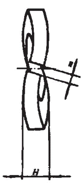
[0030] First of all, through mechanical processing, such as figure 1 The body shown is a wave spring with several sinusoidally formed washer-type springs in the circumferential direction;
[0031] Then, cover a nano anti-corrosion layer on the main structure, and this nano anti-corrosion layer is made by the following steps:
[0032] (1) Add polyether diol with a molecular weight of 3000, castor oil, and organoclay into the reaction kettle for mixing, and stir to raise the temperature. When the temperature rises to 60 °C, add toluene diisocyanate dropwise and finish adding in 40 minutes;
[0033] (2) Then heat and stir at 60 ℃ for 30 minutes, then raise the temperature to 80 ℃ and heat and stir, and take samples to measure the NCO value of the end group;
[0034] (3) When the NCO reaches 3.0%, cool down to 40°C, add styrene to the reaction system, stir for 30 minutes, and vacuum degas at 40°C for 30 minutes to obtain component A—polyurethane prepolymer; the polyether The mas...
Embodiment 2
[0041] First of all, through mechanical processing, such as figure 1 The body shown is a wave spring with several sinusoidally formed washer-type springs in the circumferential direction;
[0042] Then, cover a nano anti-corrosion layer on the main structure, and this nano anti-corrosion layer is made by the following steps:
[0043] (1) Add polyether diol with a molecular weight of 3000, castor oil, and organoclay into the reaction kettle for mixing, and stir to raise the temperature. When the temperature rises to 60 °C, add toluene diisocyanate dropwise and finish adding in 45 minutes;
[0044] (2) Then heat and stir at 60 ℃ for 40 minutes, then raise the temperature to 80 ℃ and heat and stir, and take samples to measure the NCO value of the terminal group;
[0045] (3) When the NCO reaches 3.0%, lower the temperature to 40°C, add styrene to the reaction system, stir for 40 minutes, and vacuum degas at 40°C for 35 minutes to obtain component A—polyurethane prepolymer; the p...
Embodiment 3
[0052] First of all, through mechanical processing, such as figure 1 The body shown is a wave spring with several sinusoidally formed washer-type springs in the circumferential direction;
[0053] Then, cover a nano anti-corrosion layer on the main structure, and this nano anti-corrosion layer is made by the following steps:
[0054] (1) Add polyether diol with a molecular weight of 3000, castor oil, and organoclay into the reaction kettle for mixing, and stir to raise the temperature. When the temperature rises to 60°C, add toluene diisocyanate dropwise and finish adding in 50 minutes;
[0055] (2) Then heat and stir at 60 ℃ for 50 minutes, then raise the temperature to 80 ℃ and heat and stir, and take samples to measure the NCO value of the terminal group;
[0056] (3) When the NCO reaches 3.0%, cool down to 40°C, add styrene to the reaction system, stir for 50 minutes, and vacuum degas at 40°C for 40 minutes to obtain component A—polyurethane prepolymer; the polyether The...
PUM
 Abstract
Description
Claims
Application Information
 - R&D
- Intellectual Property
- Life Sciences
- Materials
- Tech Scout
- Unparalleled Data Quality
- Higher Quality Content
- 60% Fewer Hallucinations
Browse by: Latest US Patents, China's latest patents, Technical Efficacy Thesaurus, Application Domain, Technology Topic, Popular Technical Reports.
© 2025 PatSnap. All rights reserved.Legal|Privacy policy|Modern Slavery Act Transparency Statement|Sitemap|About US| Contact US: help@patsnap.com