Gas telemetering method with alarm function

A gas and functional technology, applied in the measurement of color/spectral characteristics, etc., can solve problems such as personal injury, inability to issue danger alarms, and inability to give gas concentration information, and achieve the effect of protecting personal safety.

Active Publication Date: 2013-05-08
FOCUSED PHOTONICS
View PDF6 Cites 18 Cited by
  • Summary
  • Abstract
  • Description
  • Claims
  • Application Information

AI Technical Summary

Problems solved by technology

If the leak point is near the operator's station or the diffuse area of ​​the leaked gas is already large, the operator will be placed in the area of ​​toxic or explosive gas, posing a great threat of personal injury
Since the traditional remote gas analyzer only measures the line integral concentration and cannot give gas concentration information, it cannot issue a danger alarm
Because in the measurement scene, the gas concentration is too high or the path of the light beam passing through the gas is too long will cause the line integral concentration to be too high, and it is impossible to judge whether the line integral concentration is too high due to the concentration or the distance.

Method used


Image

  • Gas telemetering method with alarm function
  • Gas telemetering method with alarm function
  • Gas telemetering method with alarm function

Examples


Embodiment 1

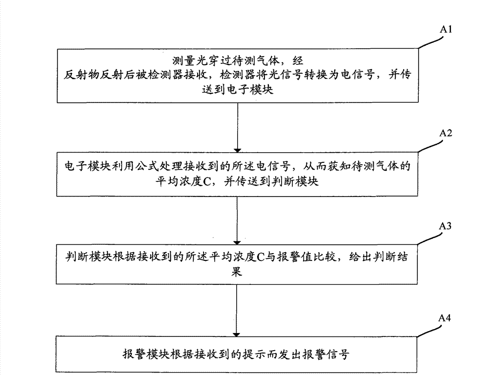
[0029] figure 2 Schematically provides the flow chart of the gas telemetry method with alarm function in the embodiment of the present invention, as figure 2 As shown, the telemetry method includes the following steps:

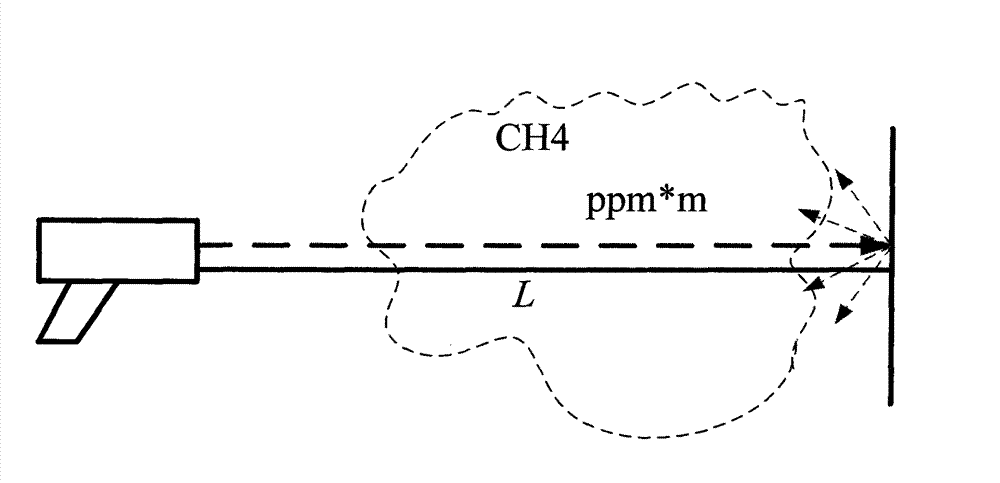
[0030] (A1) The measurement light emitted by the measurement light source passes through the gas to be measured, and the measurement light is reflected by the reflector and received by the detector, and the detector converts the optical signal into an electrical signal and transmits it to the electronic module; as a preference, The measurement light source is a semiconductor laser.

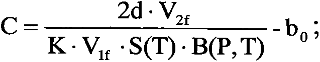
[0031] (A2) The electronic module uses the following formula to process the received electrical signal, thereby knowing the average concentration C of the gas to be measured, and sending it to the judgment module:

[0032] C = 2 d · V 2 ...

Embodiment 2

[0041] The gas telemetry method with alarm function of the embodiment of the present invention is different from Embodiment 1 in that:

[0042] In or before step (A1), the amplitude modulation of the positioning light emitted by the positioning light source is performed and the phase delay generated by one round trip of the modulated light is measured, and the electronic module converts the distance d represented by the phase delay according to the wavelength of the modulated light. The specific conversion method is the prior art in this field, and will not be repeated here.

[0043] Example 2:

[0044] The gas telemetry method with alarm function of the embodiment of the present invention is different from Embodiment 1 in that:

[0045] In the step (A1), the measuring light is modulated and a pulse signal is superimposed, and the pulse signal of the received reflected light signal is detected, and the electronic module calculates the distance d by comparing the time differen...


PUM


Abstract

The invention provides a gas telemetering method with an alarm function. The gas telemetering method comprises the following steps that: A1, measurement light emitted from a measurement light source passes through to-be-detected gas, and is received by a detector after being reflected by a reflector, the detector converts an optical signal into an electric signal, and the electric signal is transmitted to an electronic module; A2, the electronic module processes the received electric signal by a formula so as to obtain the average concentration C of the to-be-detected gas, and the average concentration C is transmitted to a judging module; A3, the judging module compares the received average concentration C with an alarm value, wherein if the average concentration C is less than the alarm value, the alarming is not needed, but if the average concentration C is more than or equal to the alarm value, a prompt is sent to the alarm module; and A4, the alarm module sends an alarm signal according to the received prompt. The gas telemetering method has the advantages of preventing people from straying in a high-concentration harmful gas region, protecting personal safety and the like.

Description

technical field [0001] The invention relates to gas detection, in particular to a gas remote measurement method with an alarm function. Background technique [0002] The remote measurement gas analyzer has the characteristics of non-contact, portable and flexible movement. Its principle is usually to use optical methods to emit a beam of light, and then receive the light that is blocked and reflected by objects. If there is a gas to be measured on the optical path, it can be used The principle of gas absorption spectroscopy measures the concentration of a gas. [0003] figure 1 The measurement scene diagram of the above-mentioned gas analyzer is schematically given, as shown in figure 1 shown. However, due to the irregular shape of the air mass leaked into the atmosphere, it is impossible to know exactly how far the light travels in the gas, so usually the telemetry gas analysis can only measure the concentration of the distance integral, that is, ppm*m. The actual avera...

Claims


Application Information

Patent Timeline
Patent Type & Authority Applications(China)
IPC IPC(8): G01N21/31G01N21/39
Inventor 俞大海邱梦春桑强
Owner FOCUSED PHOTONICS
Why Eureka
Try Eureka