Distributed energy system design method

A distributed energy and system design technology, applied in computing, special data processing applications, instruments, etc., can solve the problems of not considering the influence of time load, and cannot reflect the interaction and connection of thermoelectric and cooling loads, so as to improve system utilization, The effect of high energy utilization efficiency and good cost performance

Active Publication Date: 2013-05-08
廊坊新奥泛能网络科技服务有限公司
View PDF1 Cites 29 Cited by
  • Summary
  • Abstract
  • Description
  • Claims
  • Application Information

AI Technical Summary

Problems solved by technology

This method does not consider the influence of time and other factors on the load, and...

Method used


Image

  • Distributed energy system design method
  • Distributed energy system design method
  • Distributed energy system design method

Examples


Embodiment Construction

[0019] In order to make the object, technical solution and advantages of the present invention clearer, the present invention will be described in further detail below in conjunction with specific embodiments and with reference to the accompanying drawings. While illustrations of parameters including particular values ​​may be provided herein, it should be understood that parameters need not be exactly equal to the corresponding values, but rather may approximate the values ​​within acceptable error margins or design constraints.

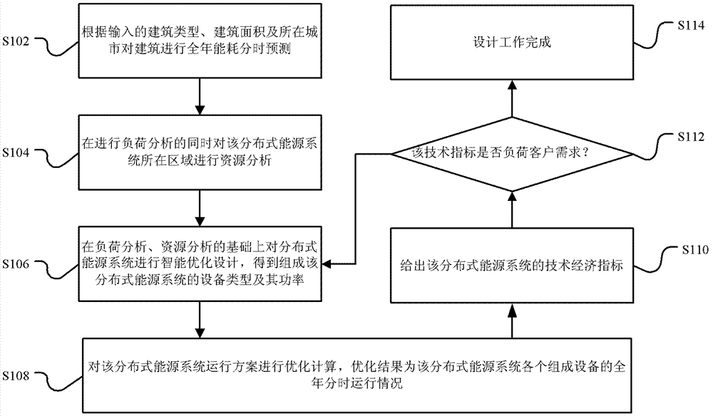
[0020] figure 1 It is a flowchart of a distributed energy system design method according to an embodiment of the present invention. Such as figure 1 As shown, the design method of this embodiment includes:

[0021] Step S102, according to the input building type, building area and city where the annual energy consumption of all buildings is time-shared, and the energy consumption of all buildings powered by the distributed energy system is summed ...


PUM


Abstract

The invention discloses a distributed energy system design method which includes the steps: acquiring annual energy consumption time-sharing load information of a distributed energy system; acquiring available energy types and resource quantity of the distributed energy system; and performing equipment selection optimization calculation based on the annual energy consumption time-sharing load information, the available energy types and the resource quantity to obtain equipment types and the power of the distributed energy system. In the design method, the distributed energy system is selected by an optimization algorithm according to annual hourly load conditions and resource availability, the problem of too large selection scale of the energy system is solved, equipment selection is decreased, and accordingly, investment for the system is reduced.

Description

technical field [0001] The invention relates to the technical field of energy comprehensive utilization, in particular to a distributed energy system design method. Background technique [0002] As the world suffers from energy shortages, distributed energy has gradually demonstrated its unique advantages. Distributed energy system refers to energy ladder utilization and comprehensive utilization of resources distributed on the demand side, as well as comprehensive utilization of resources and renewable energy facilities. At the demand and resource sites, according to the different needs of users for various energy sources, temperature-matched cascade energy supply is realized. , to minimize the loss of the transmission link, so as to realize the optimization of energy utilization efficiency. [0003] Existing distributed energy system design methods usually use static simulation methods such as degree day method and full load coefficient method to calculate the energy syst...

Claims


Application Information

Patent Timeline
IPC IPC(8): G06F17/50
Inventor 张凡李俊
Owner 廊坊新奥泛能网络科技服务有限公司
Why Eureka
Try Eureka