Light-emitting diode packaging module

A technology for light-emitting diodes and packaging modules, which is applied in electrical components, electrical solid-state devices, circuits, etc., and can solve problems such as inability to achieve

Inactive Publication Date: 2013-05-08
LIGHTEN
View PDF3 Cites 2 Cited by
  • Summary
  • Abstract
  • Description
  • Claims
  • Application Information

AI Technical Summary

Problems solved by technology

However, in addition to the problem of heat dissipation, most LED lamps emit light in a straight direction, which cannot achieve the effect of emitting light at 270 degre

Method used


Image

  • Light-emitting diode packaging module
  • Light-emitting diode packaging module
  • Light-emitting diode packaging module

Examples


Embodiment Construction

[0023] Its detailed description is as follows, and the preferred embodiment is only for illustration and not intended to limit the present invention. Figure 1A , Figure 1B and Figure 1C It is a schematic diagram of an LED packaging module according to an embodiment of the present invention.

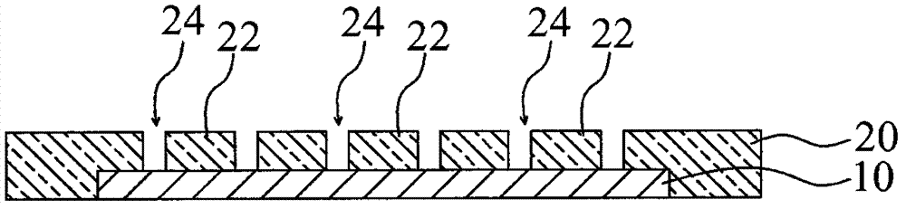
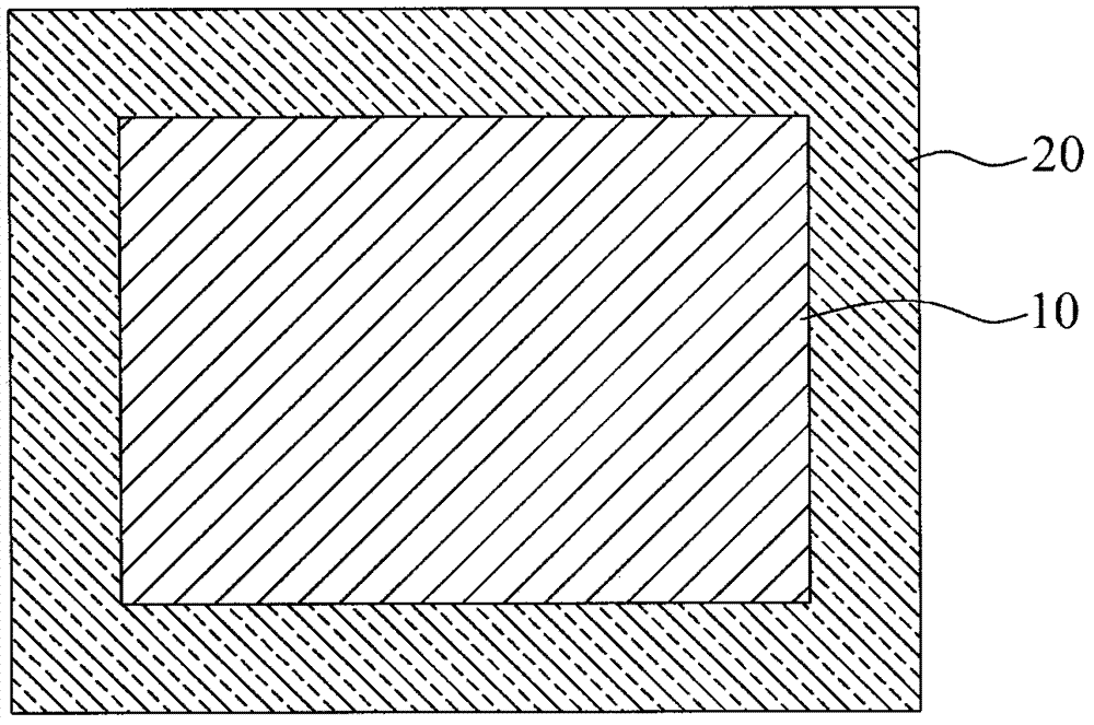
[0024] In this example, if Figure 1A As shown, the LED packaging module includes a circuit board 10 . A metal plate 20 directly covers the entire upper surface of the circuit board 10 . The metal plate 20 has a plurality of chip carriers 22 and a plurality of openings 24 . The opening 24 exposes a wire bonding area on the upper surface of the circuit board 10 . The opening 24 is disposed adjacent to the chip carrier 22 .

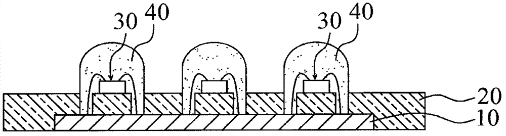
[0025] Next, please refer to Figure 1B , a plurality of chips 30 are respectively arranged on each chip carrier 22 one by one. A plurality of wires (not shown in the figure) are electrically connected to the bonding area of ​​the chip 30 and the circuit board...


PUM


Abstract

Provided is a light-emitting diode packaging module. The light-emitting diode packaging module comprises a circuit board, a metal plate, a plurality of chips, a plurality of wires and a packaging material, wherein the metal plate is used for directly covering the upper surface of the whole circuit board, the metal plate is provided with a plurality of chip bearing seats and a plurality of openings formed in a routing area which enables the circuit board to expose, the plurality of openings are arranged on the sides of the plurality of chip bearing seats in an adjoining mode, the plurality of chips are respectively arranged on each chip bearing seat, the plurality of wires are electrically connected with the chips and the routing area of the circuit board, and the packaging material is used for respectively covering each chip, the plurality of wires and the routing area.

Description

technical field [0001] The invention relates to a light emitting diode packaging technology, in particular to a light emitting diode packaging module utilizing chip on board (COB) technology. Background technique [0002] Because light-emitting diodes (light-emitting diodes, LEDs) have the characteristics of long life, power saving, and durability, LED lighting devices are a trend of green energy and environmental protection, and will be widely used in the future. In general high-brightness LED lamps, a light-emitting module that usually includes several LED bulbs is directly welded on a general circuit board or an aluminum substrate. In order to increase the heat dissipation effect, additional heat dissipation components are designed, such as heat dissipation fins are arranged under the substrate. However, in addition to the problem of heat dissipation, most LED lamps emit light in a straight direction, which cannot achieve the effect of emitting light at 270 degrees like ...

Claims


Application Information

Patent Timeline
IPC IPC(8): H01L33/60H01L33/64H01L25/075
CPCH01L2224/48091H01L2224/48228H01L2924/00014
Inventor 彭国峯
Owner LIGHTEN
Why Eureka
Try Eureka