Protective device and waterproof and humidity-proof processing mechanism used for cable ground exposing position
A protective device and moisture-proof treatment technology, which is applied in the direction of connection insulation, base/housing, etc., can solve the problems of potential safety hazards, shortened service life of cables, and aging of electrical tapes, so as to improve power transmission efficiency, avoid waste of resources, and use long life effect
- Summary
- Abstract
- Description
- Claims
- Application Information
AI Technical Summary
Problems solved by technology
Method used
Image

Examples
Embodiment 1
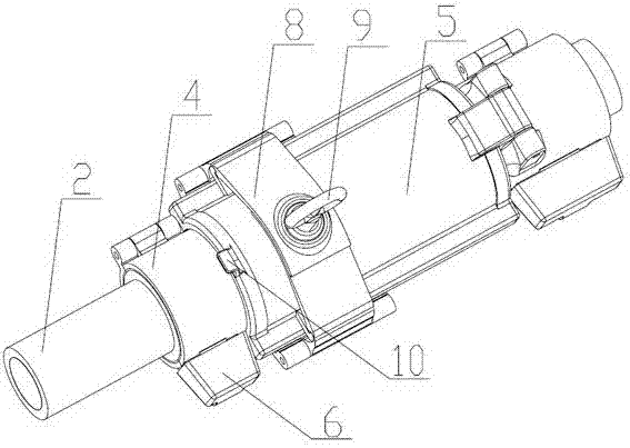
[0048]A protective device for the bare grounding of cables, including a protective shell, the protective shell includes a mating outer end protective shell 4 and a mating middle protective shell 5, which form openings at both ends after the mating, and the side-closed cable passing through The wire cavity, the middle protective shell 5 is arranged on one end of the outer protective shell 4 and is flexibly connected with it. When the outer protective shell 4 is in use, it is set on the cable sheath at the outer end of the exposed part of the cable ground. When the middle protective shell 5 is in use, Cover the exposed cable ground. Wherein, there can be one outer pair of protective shells 4 with the middle protective shell arranged at one end thereof, or two, with the middle protective shell set between the outer protective shells. Wherein the outer end protective shell 4 comprises two or more outer end sub-shells, the side of a pair of adjacent two outer end sub-shells is hing...
Embodiment 2
[0051] On the basis of embodiment 1, this embodiment has been improved as follows:
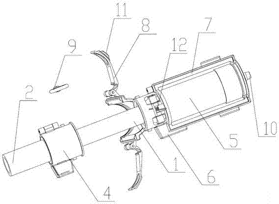
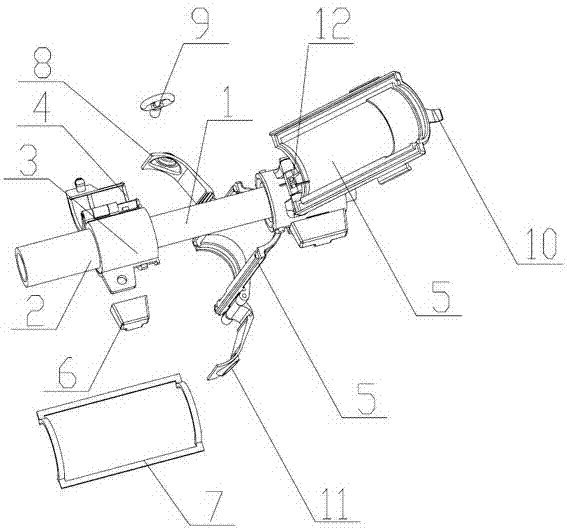
[0052] An automatic pop-up device for the middle split case, such as a torsion spring mechanism 12, is provided at the hinge joint between the middle split case and the outer end protective case 4 of the protection device for the exposed part of the cable wire.
[0053] An automatic pop-up device for the middle split case, such as a torsion spring mechanism 12, is provided at the hinge joint between the middle split case and the outer end protective case 4 of a waterproof and moisture-proof treatment mechanism for the exposed part of the cable wire.
[0054] When grounding is required for maintenance, the difference from Embodiment 1 is that after opening the locking shell 8, the middle sub-shell automatically pops open, exposing the metal foil wrapped around the grounding part, that is, the grounding wire. The buckle 10 that shell is opened.
Embodiment 3
[0056] On the basis of embodiment 2, this embodiment has been improved as follows:
[0057] A locking device for a protective device used for the bare grounding of cables is changed to include two mated locking half-shells 13, the two are movably connected, and the inner diameter of the cavity formed by mating is the same as that of the middle protective shell 5. diameter to match. One end of the locking device is arranged on the outer periphery of the outer protective shell 4, the other end is arranged on the outer periphery of the middle protective shell 5, and at least one locking half shell 13 is provided with a first baffle plate 16 near the inner side of the middle protective shell 5, the first baffle plate 16 The inner circular arc matches the outer diameter of the outer protective shell 4, and the outer protective shell 4 is provided with a limit baffle 15, and a compression spring 14 is arranged on the outer side of the outer protective shell, corresponding to the lim...
PUM
 Abstract
Description
Claims
Application Information
PatSnap Eureka turns technology decisions into work you can execute. Powered by our Innovation Knowledge Graph, it runs expert workflows across engineering, life sciences, materials and intellectual property. Get your review-ready output in minutes.


