Cooling fin machining tool and machining process

A processing technology and heat sink technology, applied in metal processing, metal processing equipment, metal processing mechanical parts, etc., can solve the problems of inability to carry out continuous production and processing, low manufacturing efficiency, and high equipment cost, and achieve improved safety and processing. The effect of short time and improved production efficiency

Active Publication Date: 2013-05-15
SICHUAN HUALI ELECTRONICS
View PDF5 Cites 6 Cited by
  • Summary
  • Abstract
  • Description
  • Claims
  • Application Information

AI Technical Summary

Problems solved by technology

[0005] 1. Technical work that requires high equipment costs and requires a certain professional foundation;
[0006] 2. Low manufacturing efficiency;
[0007] 3. The connection effect between processes is poor, because the heat sink needs to be manually transported to the milling equipment after cutting the heat sink in the cutting process, and continuous production and processing cannot be carried out

Method used


Image

  • Cooling fin machining tool and machining process
  • Cooling fin machining tool and machining process
  • Cooling fin machining tool and machining process

Examples


Embodiment

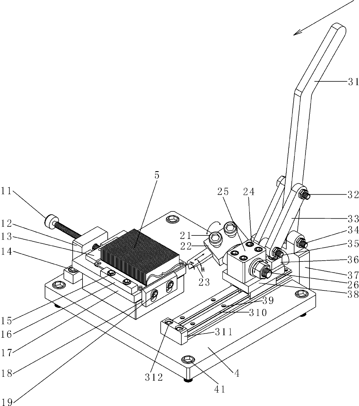
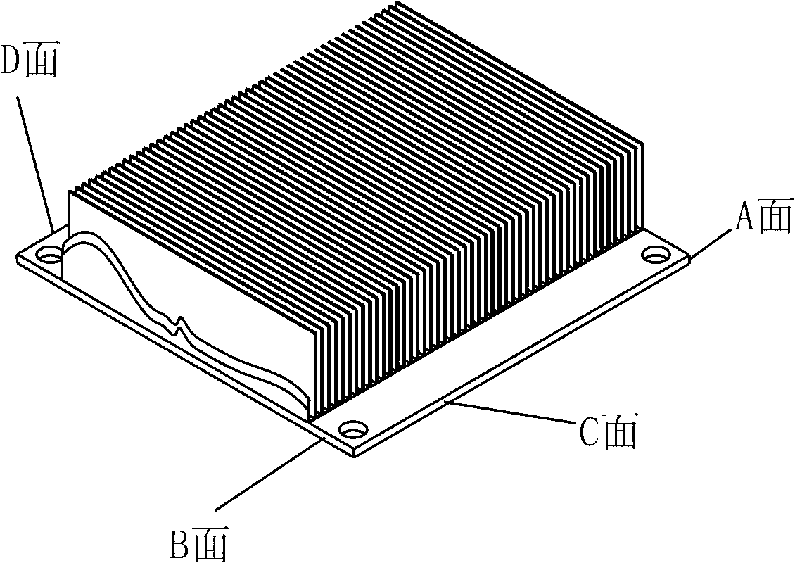
[0034] Such as figure 1 As shown, the heat sink processing tooling provided by the present invention includes a fixing seat 4, a workpiece fixing mechanism, a tool mechanism and a power mechanism; the fixing seat 4 is mainly used to fix the workpiece fixing mechanism and the power mechanism to ensure the precise positioning of each component during the cutting process; The fixed seat 4 is fixed on the production line by the second fixed seat screw rod 41, which is convenient for installation and disassembly, and facilitates the process arrangement; as image 3 As shown, the workpiece to be processed has A surface, B surface, C surface and D surface.

[0035] The workpiece fixing mechanism is installed on the fixing seat 4, so that the workpiece 5 does not move when subjected to an external force, and ensures that the tool can successfully complete the process when cutting the remaining burrs and gears; the workpiece fixing mechanism includes a first positioning block 17, an ad...


PUM


Abstract

The invention discloses a cooling fin machining tool which is characterized by comprising a fixing base, a work-piece fixing mechanism, a power mechanism and a cutter mechanism. The work-piece fixing mechanism and the power mechanism are fixed on the fixing base. The cutter mechanism is connected with the power mechanism and used for cutting off burrs and tooth pieces remaining on cooling fins. The tool can effectively remove the burrs and the tooth pieces remaining on the blanking edges of the cooling fins, replaces machine tool machining, saves cost, ensures quality, improves production efficiency, prevents short circuit or burnout of electronic components due to the fact that metal chips fall on the electronic components when the tool is applied to the electronic components, and improves safety.

Description

technical field [0001] The invention belongs to the technical field of electronic component heat sink processing equipment and processing technology, and in particular relates to a heat sink processing tool and processing technology, which are used for cutting burrs and tooth pieces remaining on the cutting edge of the heat sink. Background technique [0002] As we all know, in order to ensure the normal operation of electronic components (main board, circuit board, etc.), it is usually necessary to install heat sinks on the side and / or upper part of the electronic components, and the heat sink plays the role of reducing the temperature rise of electronic components. During the processing of the heat sink, the heat sink is usually cut by a sawing machine or other similar equipment, and then enters the subsequent process such as CNC finishing. However, after cutting the heat sink, there will be very sharp burrs and tooth residues in the cutting part, and these residual burrs ...

Claims


Application Information

Patent Timeline
Patent Type & Authority Applications(China)
IPC IPC(8): B23D79/00B23Q3/00B23Q5/22B23Q15/22
Inventor 陈勇常青保
Owner SICHUAN HUALI ELECTRONICS
Why Eureka
Try Eureka