
A tensile stress rapid corrosion test machine for samples

A rapid corrosion and testing machine technology, applied in the direction of weather resistance/light resistance/corrosion resistance, measuring devices, instruments, etc., can solve the problems of arm error, affect the experimental effect, can not be found in time, etc., to speed up the experimental cycle and test data. Accurate and guaranteed comparable results

Active Publication Date: 2015-08-26
龙口市丛林铝材有限公司
View PDF6 Cites 0 Cited by
  • Summary
  • Abstract
  • Description
  • Claims
  • Application Information

AI Technical Summary

Problems solved by technology

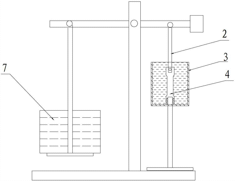
The stress corrosion testing machine used in the past such as figure 1 As shown, it adopts the lever principle to load the tension, which has the following defects. First, the concentration of the corrosive liquid around the sample becomes smaller as the corrosion time prolongs, making the test period long; second, the mechanism directly affects the The size of the torque and the friction of the three axes will change with the extension of time, and the resistance will also change continuously. The difference in the degree of lubrication will also affect the experimental results.
In addition, the verticality of the applied force will also vary from person to person, all of which obviously have many uncertain factors
Therefore, the obtained results need to be rounded up. The amount of rounding up is more appropriate, and there is no clear standard. In the actual testing work, there are often disputes between the supply and demand sides. Specimen to be processed

Method used


Image

  • A tensile stress rapid corrosion test machine for samples
  • A tensile stress rapid corrosion test machine for samples
  • A tensile stress rapid corrosion test machine for samples

Examples


Embodiment Construction

[0022] The principles and features of the present invention are described below in conjunction with the accompanying drawings, and the examples given are only used to explain the present invention, and are not intended to limit the scope of the present invention.

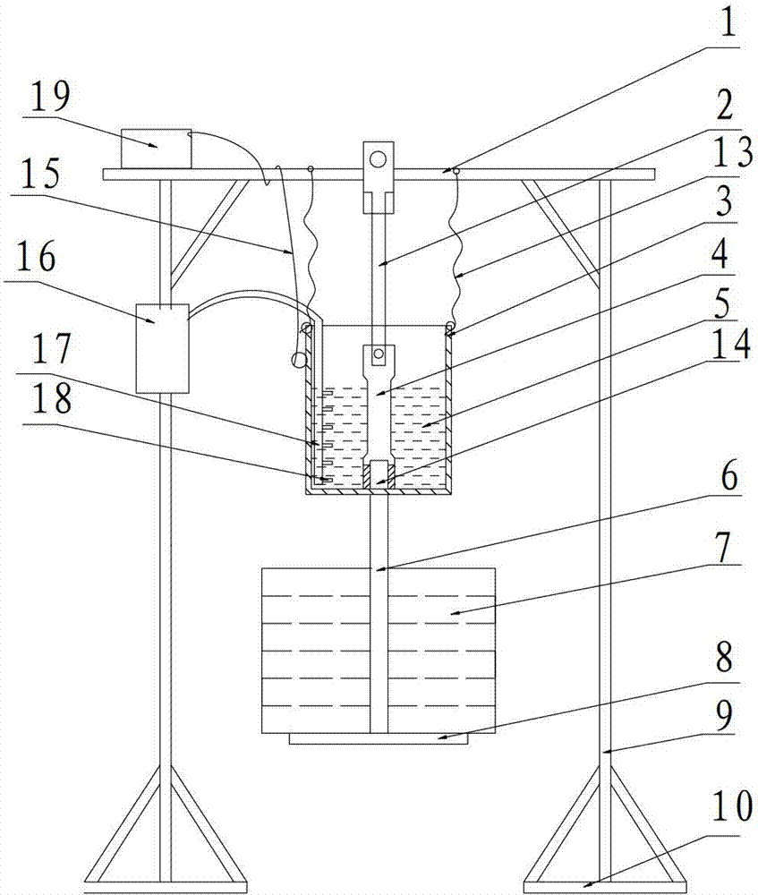
[0023] Such as Figure 2~4 As shown, a sample tensile stress rapid corrosion test machine includes a corrosion cup 3 and a timing stirring device for the corrosion solution. The corrosive liquid timing stirring device includes a main air pipe 17 inserted in the corrosion cup 3 , a branch air pipe 18 connected to the main air pipe 17 and an air pump 16 connected to the main air pipe 17 . During specific implementation, the air pump 16 is controlled by a timer, such as stirring for 10 seconds after 1 hour, to effectively ensure the concentration of the corrosion solution around the sample.

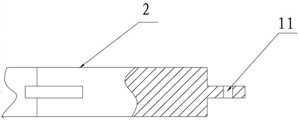
[0024] It also includes a bracket, a weight 7, an upper draw bar 2 and a lower draw bar 6, the support includes a beam 1, the u...


PUM


Abstract

The invention relates to a rapid test sample tensile stress corrosion tester which comprises a corrosive cup and a corrosive liquid timing stirring device, wherein the corrosive liquid timing stirring device comprises a main air tube which is inserted into the corrosive cup, branch air tubes connected with the main air tube and an air pump connected with the main air tube; the tester further comprises a bracket, weights, an upper traction rod and a lower traction rod, wherein the bracket comprises a transverse beam; the upper end of the upper traction rod is connected with the transverse beam; the lower end of the upper traction rod is connected with a test sample; the upper end of the lower traction rod is fixedly connected with the bottom end of the corrosive cup; a weight base is arranged at the lower end of the lower traction rod; the weights are stacked on the weight base; a safety rope which is fixedly connected with the transverse beam is further arranged at the upper part of the corrosive cup; and the tester further comprises a test sample breakage timing alarm device. The tester has the beneficial effects that the structure is simple, the detection data are accurate and reliable, and different alloy test samples can be adjusted by the weights, with convenience in use.

Description

technical field [0001] The invention relates to the technical field of metal material detection, in particular to a sample tensile stress rapid corrosion testing machine. Background technique [0002] In industrial production, tensile stress corrosion tests are required for materials used in key parts of some products. For example, the corbel beam applied to the "motor car" is the main component of the "motor car" assembly vehicle, which requires a high-strength, weldable, and corrosion-resistant 7N01 alloy. Before assembly, its corrosion resistance must be tested. Stress corrosion testing machines used in the past such as figure 1 As shown, it adopts the lever principle to load the tension, which has the following defects. First, the concentration of the corrosive liquid around the sample becomes smaller as the corrosion time prolongs, making the test period long; second, the mechanism directly affects the The size of the torque and the friction of the three axes will cha...

Claims


Application Information

Patent Timeline
Patent Type & Authority Patents(China)
IPC IPC(8): G01N17/00
Inventor 王刚张培良王惠勇王明坤孙本良
Owner 龙口市丛林铝材有限公司
Learn More