Flywheel energy storage rotor shaft

A flywheel energy storage and rotor shaft technology, which is applied in the direction of controlling mechanical energy, electrical components, electromechanical devices, etc., can solve the problems of motor rotor imbalance, rotor forced vibration, etc., and achieve the effect of smooth operation, vibration reduction and noise reduction

Inactive Publication Date: 2013-05-15
CHINA PETROLEUM & CHEM CORP +2
View PDF6 Cites 18 Cited by
  • Summary
  • Abstract
  • Description
  • Claims
  • Application Information

AI Technical Summary

Problems solved by technology

[0003] The purpose of the present invention is to provide a high-speed flywheel energy storage rotor shaft in order to overc

Method used


Image

  • Flywheel energy storage rotor shaft

Examples


Embodiment Construction

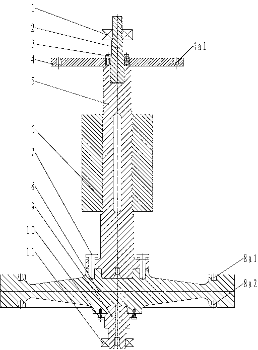
[0011] Such as figure 1 As shown, the present invention consists of an upper bearing 1, a non-magnetic shaft 2, a motor rotor mandrel 5, a motor rotor 6, a flywheel 8, a lower end shaft 9 and a lower bearing 11, and a dynamic balancing process is installed on the upper end of the motor rotor mandrel 5 Disk 4. The entire flywheel rotor shaft adopts a vertical structure. The flywheel rotor shaft is supported on the upper bearing 1 and the lower bearing 11. The connecting bolt 3 connects the non-magnetic shaft 2 and the motor rotor core shaft 5, and the motor rotor 6 is sleeved on the motor rotor core shaft 5, and the torque is transmitted by the key. The flywheel connecting bolt 7 connects the flywheel 8 and the motor rotor core shaft 5 . The lower end shaft 9 is connected with the flywheel 8 through the lower end shaft connecting bolt 10 .

[0012] The dynamic balancing process plate 4 is a plate structure, and its upper part is processed with an annular dovetail groove 4a...


PUM


Abstract

The invention provides a flywheel energy storage rotor shaft device which comprises an upper bearing, a nonmagnetic shaft, a motor rotor mandril, a motor rotor, a flywheel, a lower end shaft and a lower bearing. A dynamic balance process plate is arranged at the upper end of a motor rotor shaft. Due to the fact that the dynamic balance process plate is arranged at the upper end of the motor rotor shaft, when the flywheel rotates in a high speed, the flywheel can reach balance, vibration in operation is reduced, device noise in the operation is reduced and the whole device can operate stably. Meanwhile, a structure of the flywheel is in a dumbbell shape and stress level of the flywheel is lower than that of a hollow flywheel by 50%. The thickness of an outer flange of the flywheel is increased and rotational inertia of the flywheel is improved.

Description

technical field [0001] The invention relates to a flywheel energy storage rotor shaft, belonging to the technical field of flywheel power storage devices. Background technique [0002] With the rapid development of new energy power generation and electric vehicles, flywheel energy storage technology and flywheel rotation speed are developing towards high speed, and the application of flywheel energy storage devices will be more extensive. Chinese patent CN202260819 discloses a disk-type flywheel energy storage device, which includes a housing, inside which are installed a stator disk, a rotating shaft, rotor 1 and rotor 2, and the two ends of the rotating shaft are respectively supported on the housing through bearings; the stator disk is located on the Between rotor one and rotor two, and the central opening of the stator disk is for the shaft to pass through, and the edge is fixedly connected to the inner wall of the housing. Torque can be transmitted. During the manufac...

Claims


Application Information

Patent Timeline
IPC IPC(8): H02K7/02
CPCY02E60/16
Inventor 张超平戴兴建李伟廷张玉甫秦晓峰李胜忠
Owner CHINA PETROLEUM & CHEM CORP
Why Eureka
Try Eureka