Metal die preheating device and metal die preheating technology thereof

A metal mold and preheating device technology, applied in the field of metal mold preheating device and metal mold preheating process, can solve the problems of large local temperature difference, prolonged preheating time, uneven combustion, etc., to achieve small local temperature difference, Easy to make, evenly heated effect

Active Publication Date: 2013-05-22
WENZHOU RUIMING IND
View PDF4 Cites 12 Cited by
  • Summary
  • Abstract
  • Description
  • Claims
  • Application Information

AI Technical Summary

Problems solved by technology

Due to the large number of metal molds, irregular shape, relatively large size, and irregular position distribution (especially the sprue cup) of some products, and affected by these factors, most of the current preheating processes use two guns to face the mold The cavity is sprayed and burned. This process will lead to uneven combustion and large local temperature differences, which will lead to uneven heating of the mold and shortened life; if the temperature meets the relevant requirements, the local temperature will be too high, wasting gas, Waste of time and increase cost; if only the local temperature meets the requirements, the first few products produced will be wasted as ironing molds (i.e. waste products), increasing the cost of materials, labor and gas
In addition, the sprue cup and the mold cavity cannot be heated at the same time due to the position problem, and the resulting sequence leads to longer preheating time and waste of fuel, etc.

Method used


Image

  • Metal die preheating device and metal die preheating technology thereof
  • Metal die preheating device and metal die preheating technology thereof
  • Metal die preheating device and metal die preheating technology thereof

Examples


Embodiment Construction

[0012] The technical solution of the present invention is further specifically described in conjunction with examples.

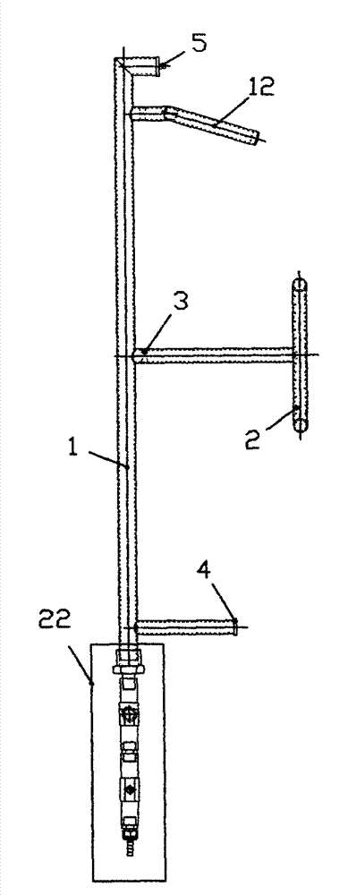
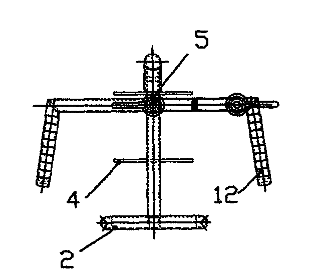
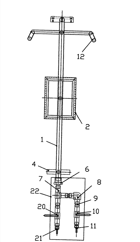
[0013] refer to Figure 1 to Figure 3 , the metal mold preheating device of the present invention includes a heating main pipe 1, a first branch branch pipe 2 is installed under one end of the heating main pipe 1, and a second branch branch pipe 12 is installed under the other end of the heating main pipe 1. The starting end (through the internal and external wire joint 6) is equipped with a three-way joint 7, and one end of the three-way joint 7 is equipped with a first joint 21 through the first valve 20 (ball valve class), and its other end passes through (right-angle inner pair of wire joints 8, The outer pair of wire joints 9 and) the second valve 10 (ball valve class) is equipped with a second joint 11.

[0014] Wherein: the both sides of described heating main pipe 1 are respectively equipped with balance piece 4, positioning pin 5, as being installe...


PUM


Abstract

The invention provides a metal die preheating device. A first split-flow branch pipe and a second split-flow branch pipe are respectively arranged at two ends of a heating main pipe, and an initial end of the heating main pipe is provided with a tee connector which is respectively provided with a first connector through a first valve and a second connector through a second valve. The metal die preheating technology of the metal die preheating device includes the steps of firstly opening dies at two sides of a metal die, then fixing the metal die preheating device on the metal die so that the first split-flow branch pipe is floated in a shape cavity of the metal die and the second split-flow branch pipe is floated in a pouring gate of the metal die, then connecting a fuel source on the first connector and connecting a pneumatic supply on the second connector, opening valve switches so that fuel gas flows into the two split-flow branch pipes through the heating main pipe to be ignited and burned after flowing out of nozzles, and adjusting size of flame by adjusting switches of two valves until the metal die is evenly heated to reach relevant technology parameters. The metal die preheating device and the metal die preheating technology of the metal die preheating device has the advantages of being capable of solving the problems that the existing die is low in service life, long in heating time, high in cost, large in labor intensity of workers and unstable in the technology parameters.

Description

technical field [0001] The invention relates to a metal mold preheating device and a preheating process thereof for gravity casting and low pressure casting casting processes of aluminum parts, in particular to a metal mold preheating device and a metal mold preheating process thereof. Background technique [0002] At present, before the production of aluminum alloy products (aluminum parts) by gravity casting and low-pressure casting processes, it is necessary to preheat the metal molds, heat each mold evenly and heat it to 300±50°C (the process requirements of different products are different) Then start pouring the product. Due to the large number of metal molds, irregular shape, relatively large size, and irregular position distribution (especially the sprue cup) of some products, and affected by these factors, most of the current preheating processes use two guns to face the mold The cavity is sprayed and burned. This process will lead to uneven combustion and large lo...

Claims


Application Information

Patent Timeline
Patent Type & Authority Applications(China)
IPC IPC(8): B22D27/04
Inventor 叶锦瑞郭剑戴光永赵晓光
Owner WENZHOU RUIMING IND
Why Eureka
Try Eureka