R-angle stamping fixture for flexible milled-surface-painted plastic material

A technology of surface coating and plastic materials, applied in the direction of milling machine equipment, manufacturing tools, milling machine equipment details, etc., can solve the problems of large occupied area, paint cracks around the radar hole, high equipment cost, etc., and achieve the effect of ensuring smoothness

Active Publication Date: 2013-05-22
YANFENG PLASTIC OMNIUM AUTOMOTIVE EXTERIOR SYST
View PDF6 Cites 0 Cited by
  • Summary
  • Abstract
  • Description
  • Claims
  • Application Information

AI Technical Summary

Problems solved by technology

[0002] On the surface of metal workpieces, it is often necessary to form the R angle of the hole edge, that is, to chamfer the edge of the hole, and the same is required for plastic material products, but the R angle forming on the plastic material workpiece often uses mold or tool cutting to achieve the purpose. , it is difficult to cover the product process requirements
Such as the radar hole and cleaning hole on the front and rear bumpers of the car, it is difficult to avoid serious defects in the injection molding and coating process with mold molding, and it is difficult to meet the quality requirements of automotive exterior parts with cutting tools. The current punching device generally uses special tools for stamping machines However, the existing punching device often causes the paint on the working surface and the base material to yield and deform under force, resulting in appearance defects such as cracks and roughness in the paint around the radar hole, resulting in production waste
Moreover, the special plane is dedicated, the equipment cost is high, and the occupied area is large. With the increase of new products, many factories are unable to bear the current state

Method used


Image

  • R-angle stamping fixture for flexible milled-surface-painted plastic material
  • R-angle stamping fixture for flexible milled-surface-painted plastic material
  • R-angle stamping fixture for flexible milled-surface-painted plastic material

Examples


Embodiment Construction

[0021] The present invention will be further described now in conjunction with accompanying drawing.

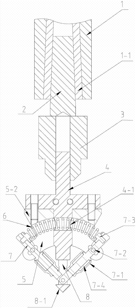
[0022] The present invention includes a robot arm, a main shaft connector, a transmission shaft, a self-tightening drill chuck, a transmission positioning main shaft, an arc-shaped housing, a roller, a ball, a central positioning column, and a spring, wherein the transmission positioning main shaft 4 adopts A vertical upper connecting shaft is provided on the top of a connecting end surface, and a vertical lower connecting shaft is arranged on the bottom of the connecting end surface, and the upper connecting shaft and the lower connecting shaft are located on the same central axis , where the transmission and positioning main shaft 4 is an integrated structure.

[0023] see Figure 4 with Figure 5 , the arc-shaped shell 5 is two arc-shaped plates that are symmetrical front and back, and the outer arcs of the tops of the two arc-shaped plates are arc-shaped closed and conn...


PUM


Abstract

The invention relates to the technical field of flexible material milling fixtures and particularly relates to an R-angle stamping fixture for a flexible milled-surface-painted plastic material. The R-angle stamping fixture is characterized in that gaps are respectively formed in the two ends of the arc-shaped closure of the upper part of an arc-shaped shell body; the lower plane of the connecting end face of a transmission and locating main shaft is fixedly connected with the upper surface of the top of the arc-shaped shell body, the bottom end of the lower connecting shaft part of the transmission and locating main shaft penetrates through the middle of the top of the arc-shaped shell body and is then located below the arc-shaped shell body, and the bottom face of the lower connecting shaft part of the transmission and locating main shaft is connected with the top end of a center locating column; the bottom ends of two cylindrical rollers are respectively pinned to the front side of the lower part of the center locating column, the top ends of the two cylindrical rollers are respectively embedded in the gaps of the left and right ends of the arc-shaped shell body, the left end of a spring is fixed to the top of a left cylindrical roller, and the right end of the spring penetrates through a spring hole of the transmission and locating main shaft and is then fixed to the top of a right cylindrical roller; and rolling balls are sleeved outside the middle parts of the cylindrical rollers. Compared with the prior art, the R-angle stamping fixture has the advantage that the defects caused by the surface yielding and deformation stress of workpieces can be overcome.

Description

technical field [0001] The invention relates to the technical field of flexible material milling tooling, in particular to an R-angle pressing tooling for plastic materials coated with paint on the surface of flexible milling. Background technique [0002] On the surface of metal workpieces, it is often necessary to form the R angle of the hole edge, that is, to chamfer the edge of the hole, and the same is required for plastic material products, but the R angle forming on the plastic material workpiece often uses mold or tool cutting to achieve the purpose. , it is difficult to cover the product process requirements. Such as the radar hole and cleaning hole on the front and rear bumpers of the car, it is difficult to avoid serious defects in the injection molding and coating process with mold molding, and it is difficult to meet the quality requirements of automotive exterior parts with cutting tools. The current punching device generally uses special tools for stamping mac...

Claims


Application Information

Patent Timeline
IPC IPC(8): B23C3/12
Inventor 李育弟
Owner YANFENG PLASTIC OMNIUM AUTOMOTIVE EXTERIOR SYST
Why Eureka
Try Eureka