Forming and milling process of automotive differential clutch engagement sleeve

A meshing sleeve and clutch technology, applied in the direction of elements with teeth, gear teeth, belts/chains/gears, etc., can solve the problems of rising processing costs, low processing efficiency, high labor intensity of workers, etc., to reduce processing costs, The effect of improving processing efficiency and simplifying processing procedures

Inactive Publication Date: 2013-05-22
QIJIANG YONGYUE GEAR
View PDF8 Cites 5 Cited by
  • Summary
  • Abstract
  • Description
  • Claims
  • Application Information

AI Technical Summary

Problems solved by technology

The workpiece needs to be clamped and positioned between each process, resulting in hig

Method used


Image

  • Forming and milling process of automotive differential clutch engagement sleeve
  • Forming and milling process of automotive differential clutch engagement sleeve
  • Forming and milling process of automotive differential clutch engagement sleeve

Examples


Example Embodiment

[0022] Hereinafter, the preferred embodiments of the present invention will be described in detail with reference to the accompanying drawings.

[0023] First, the differential back milling cutter suitable for the forming and milling process of the engagement sleeve of the automobile differential clutch of the present invention will be described.
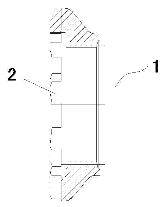
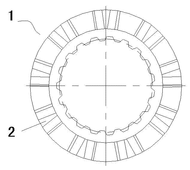
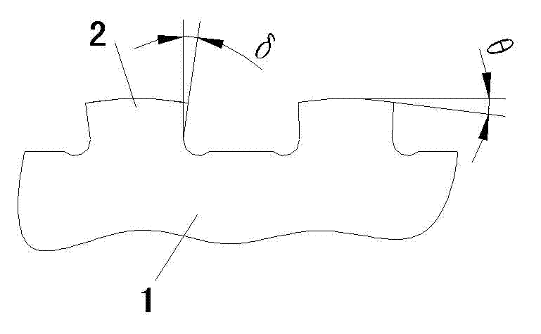
[0024] Such as Figure 4 Shown is a schematic structural diagram of a differential back milling cutter suitable for the forming and milling process of the engagement sleeve of the automobile differential clutch of the present invention. The shaped back milling cutter for the engagement sleeve of the automobile differential clutch includes a disc-shaped milling cutter body 3, and the outer peripheral wall of the milling cutter body 3 is provided with a cutter head 4 for milling meshing teeth 2, and the cutter head 4 includes Cutting edge I5 for milling the bottom surface of the meshing tooth groove, cutting edge II6 for milling one side o...


PUM


Abstract

The invention discloses a forming and milling process of an automotive differential clutch engagement sleeve. The process includes the steps: 1) clamping a workpice, mounting an engagement sleeve workpiece on an index plate, and adjusting an angle alpha between an engagement surface of the engagement sleeve workpiece and a milling machine workbench through the index plate, wherein the angle alpha is an included angle between a cutting edge I of a backoff milling cutter and an axis of the backoff milling cutter; 2) setting the cutter to enable the backoff milling cutter to be positioned in a radial direction of the engagement sleeve workpiece in a feed direction parallel to a milling machine workbench direction; 3) performing primary milling by utilizing the backoff milling cutter to mill a side tooth crest, a side tooth flank and a side tooth socket on the engagement sleeve workpiece; 4) rotating the engagement sleeve workpiece by 180 degrees; 5) performing secondary milling by utilizing the backoff milling cutter to mill another side tooth crest, another side tooth flank and another side tooth socket on the engagement sleeve workpiece; and 6) rotating the engagement sleeve workpiece with a rotating angle equal to a mechanical angle of between two adjacent engagement teeth, and repeating the step 3) to the step 5) until all engagement teeth are machined.

Description

technical field [0001] The invention belongs to the technical field of milling, in particular to a forming milling process for an engagement sleeve of an automobile differential clutch. Background technique [0002] Such as figure 1 As shown, it is a structural schematic diagram of the meshing sleeve of the automobile differential clutch, and the meshing surface of the meshing sleeve 1 of the automobile differential clutch is uniformly arranged with meshing teeth 2 in a ring. Such as image 3 As shown, the shape and structure of the meshing teeth 2 are relatively complex. The two ends of the tooth tops of the meshing teeth 2 are provided with a tooth top bevel angle θ=7°, and the bottom width of the meshing tooth groove between two adjacent meshing teeth 2 Wider than the width of the top, that is, the inclination angle of the tooth side is δ=1°38'±3', and there is a circular arc transition between the tooth side and the groove bottom of the meshing tooth groove. Because t...

Claims


Application Information

Patent Timeline
IPC IPC(8): B23F15/06
Inventor 张集胜
Owner QIJIANG YONGYUE GEAR
Why Eureka
Try Eureka