Micro-foaming injection structure

A technology of micro-foaming and micro-cellular foaming, which is applied in the field of injection structure with micro-cellular foaming function, can solve the problems of complex hydraulic control circuit of the control system, narrow market promotion area, high cost, etc., and achieve simple and effective structure, Dimensional stability and energy saving effect

Inactive Publication Date: 2013-05-22
BORCH MACHINERY
View PDF0 Cites 8 Cited by
  • Summary
  • Abstract
  • Description
  • Claims
  • Application Information

AI Technical Summary

Problems solved by technology

However, this technical solution requires the replacement of the material tube group, especially the lengthening of the screw rod, which requires high machining accuracy. It involves a very complicated control system, especially the hydraulic control circuit, which requires high back pressure, servo valve control, etc., and reassembles and debugs the existing The cost of equipment is high, and the market promotion area is narrow

Method used


Image

  • Micro-foaming injection structure

Examples


Embodiment Construction

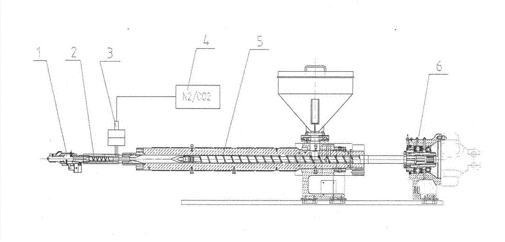
[0012] The present invention will be further described in detail below in conjunction with the accompanying drawings and embodiments.

[0013] As shown in the figure, a micro-foaming injection structure includes a rapid nozzle (1), a mixer (2), an inflator (3), a supercritical fluid generator (4), a material tube group (5), And injection part (6), it is characterized in that: add mixer (2), pumping device (3) and rapid nozzle (1) at the front end of common injection molding machine barrel group; , the injection platform advances, and then the rapid nozzle (1) is in a closed and sealed state.

[0014] At this time, the injection molding machine starts to melt the glue, the pumping device (3) is opened, and the supercritical fluid generating device (4) injects the supercritical fluid into the mixer (2) and the material tube group (5), and the injection of the supercritical fluid The ratio and speed are closed-loop controlled by the computer of the injection molding machine. Whe...


PUM


Abstract

A micro-foaming injection structure comprises a quick injection nozzle, a mixer, a bulging device, a supercritical fluid generating device, a material tube group and an injection component. The micro-foaming injection structure is characterized in that the mixer, the bulging device and the quick injection nozzle are installed on the front end of the material tube group of a universal injection molding machine; when the injection molding machine performs or finishes a plastic smelting action, the bulging device is started, the supercritical fluid generating device injects supercritical fluid in the mixer and the material tube group, and then, the injection component propels a screw to inject, and meanwhile, the quick injection nozzle opens, the raw material and the gas are further mixed through the mixer and finally enter an injection mould to realize a minipore foaming function, the micro-foaming injection structure meets the technique demands of reducing the weight of the workpieces, shortening the forming period, reducing the mould locking force of the equipment, small internal stress and warpage, high flatness, non-shrinkage and stable dimension of minipore foaming, and furthermore, the structure is simple and effective, the cost is low and the practicability is strong.

Description

Technical field [0001] The invention relates to a microfoaming injection structure, in particular to an injection structure with microcellular foaming function on an injection molding machine. Background technique [0002] In the 1980s, the Massachusetts Institute of Technology (MIT) first proposed the concept of microcellular foaming, hoping to produce high-density closed cells in the product, thereby increasing its rigidity while reducing the amount of material used, and avoiding damage to strength, etc. performance impact. The US TREXEL company was established in the mid-1990s and obtained all patent authorizations from MIT. It commercialized the microcellular foam technology and continued to vigorously develop it, which has been widely recognized in the industry. However, this technical solution requires the replacement of the material tube group, especially the lengthening of the screw rod, which requires high machining accuracy. It involves a very complicated control ...

Claims


Application Information

Patent Timeline
Patent Type & Authority Applications(China)
IPC IPC(8): B29C45/57
Inventor 黄土荣李晓静
Owner BORCH MACHINERY
Why Eureka
Try Eureka