
Free piston Stirling engine system utilizing high-low temperature heat sources meanwhile

A technology of Stirling engine and high-temperature heat source, which is applied in the direction of hot gas variable displacement engine device, machine/engine, mechanical equipment, etc., and can solve the problem of increasing friction loss between piston and cylinder, adverse effects of piston and cylinder seal, increasing Problems such as flow loss and cooling loss can be solved to achieve the effect of ensuring low cost, avoiding adverse effects, and ensuring compact structure

Active Publication Date: 2015-04-15
TECHNICAL INST OF PHYSICS & CHEMISTRY - CHINESE ACAD OF SCI
View PDF8 Cites 0 Cited by
  • Summary
  • Abstract
  • Description
  • Claims
  • Application Information

AI Technical Summary

Problems solved by technology

when using figure 1 or figure 2 In the traditional free-piston Stirling structure, the heat-absorbing end heat exchanger 12 is the high-temperature end, and the heat-releasing end heat exchanger 14 is the low-temperature end. Sealing will cause adverse effects, increasing flow loss and cooling loss; when using image 3 In the structure of a novel free-piston Stirling engine shown, the exothermic end heat exchanger 24 is a low-temperature end, the heat-absorbing end heat exchanger 22 is a high-temperature end, and the power piston 27 works in a high-temperature environment and is easy to be thermally expanded. Increase friction loss between piston and cylinder
Therefore, adopting a set of free piston engine system can never avoid the adverse effect of temperature on the sealing of the power piston and the corresponding cold and heat loss, but its advantages are compact structure and low cost

Method used


Image

  • Free piston Stirling engine system utilizing high-low temperature heat sources meanwhile
  • Free piston Stirling engine system utilizing high-low temperature heat sources meanwhile
  • Free piston Stirling engine system utilizing high-low temperature heat sources meanwhile

Examples


Embodiment 2

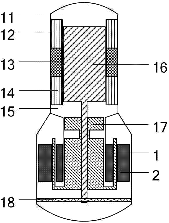
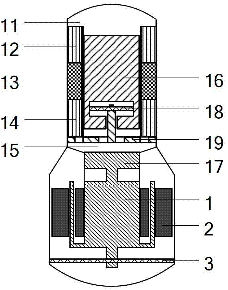
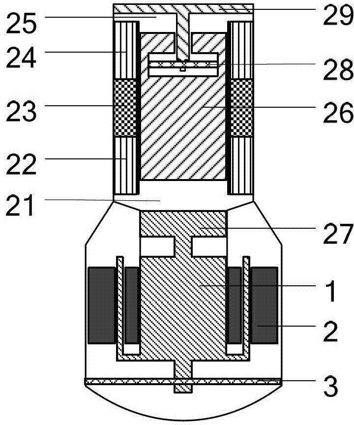
[0063] Figure 6 It is a structural schematic diagram of Embodiment 2 of the free-piston Stirling engine system utilizing both high and low temperature heat sources of the present invention. Such as Figure 6As shown, the high-temperature heat source free-piston Stirling engine and the low-temperature cold source free-piston Stirling engine are symmetrically arranged in a straight line, and the linear generator is perpendicular to the high-temperature heat source free-piston Stirling engine and the low-temperature cold source free-piston Stirling engine Arrangement, the three are connected by a three-way pipe, the high-temperature heat source is connected to the first expansion chamber 15 of the piston Stirling engine, and the low-temperature cold source is connected to the second expansion chamber 21 of the piston Stirling engine and the linear generator respectively The three branch pipes of the three-way pipe.

[0064] The structure of each component of the high-temperatu...


PUM


Abstract

A free piston Stirling engine system utilizing high-low temperature heat sources meanwhile is composed of a high-temperature heat source free piston Stirling engine, a low-temperature cold source free piston Stirling engine and a linear engine, wherein the high-temperature heat source free piston Stirling engine and the low-temperature cold source free piston Stirling engine drive the linear engine together, a structure and a arrangement method of the high-temperature heat source free piston Stirling engine are the same to that of a traditional free piston Stirling engine, a structure of the low-temperature cold source free piston Stirling engine and the structure of the traditional free piston Stirling engine are reversed, and therefore a power piston is enabled to work room-temperature environment. The free piston Stirling engine system utilizing the high-low temperature heat sources meanwhile utilizes a high-temperature heat source and a low-temperature heat source at the same time and has the advantages of being compacted in structure and low in cost. A high-temperature heat exchanger and a low-temperature heat exchanger are both arranged at the side far from the power piston, the power piston works at the room temperature, the temperature is prevented from having bad effect on sealing of the power piston, and high-efficient and stable operation of a system are guaranteed.

Description

technical field [0001] The invention relates to an engine system, in particular to a free-piston Stirling engine system utilizing high and low temperature heat sources at the same time. Background technique [0002] The Stirling engine is an external combustion engine, which generates power through the thermal expansion and cold contraction of the working medium gas inside the engine, and converts thermal energy into mechanical energy. Its theoretical efficiency is equal to the Carnot cycle efficiency. The free piston Stirling engine is a structural form of the Stirling engine. It adopts the "power piston + displacer (also called free piston)" structure instead of the "double piston" structure of the traditional Stirling heat engine. By controlling the discharge Its working characteristics are determined by parameters such as the quality of the ejector, the difference in cross-sectional area on both sides of the ejector, and the spring stiffness. At the same time, the transm...

Claims


Application Information

Patent Timeline
Patent Type & Authority Patents(China)
IPC IPC(8): F02G1/043F02G1/053
Inventor 罗二仓余国瑶李珂戴巍吴张华
Owner TECHNICAL INST OF PHYSICS & CHEMISTRY - CHINESE ACAD OF SCI
Learn More