Electro-hydraulic servo actuator

An electro-hydraulic servo and actuator technology, which is applied to fluid pressure actuators, fluid pressure actuator system components, mechanical equipment, etc., can solve the problem of single working mode of electro-hydraulic actuators, failure to realize fault self-protection, and high energy consumption and other problems, to achieve the effect of simple structure, fast response speed and high control precision

Inactive Publication Date: 2013-05-22
BEIJING MECHANICAL EQUIP INST
View PDF6 Cites 24 Cited by
  • Summary
  • Abstract
  • Description
  • Claims
  • Application Information

AI Technical Summary

Problems solved by technology

[0003] The purpose of the present invention is to provide an electro-hydraulic servo actuator, which solves the problems of traditional e...

Method used


Image

  • Electro-hydraulic servo actuator

Examples


Embodiment Construction

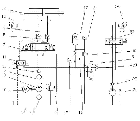
[0009] An electro-hydraulic servo actuator, including: fuel tank 1, motor 2, hydraulic pump 3, overflow valve 6, servo valve 7, hydraulic cylinder 12, pressure relay 15, accumulator 17, pressure gauge 24, and also includes: filter Device A4, filter B5, hydraulic lock A8, hydraulic lock B9, one-way valve A10, one-way valve B20, one-way valve C22, safety valve A13, safety valve B14, safety valve C18, two-position three-way solenoid valve 11, Two-position four-way solenoid valve 19, three-position four-way manual reversing valve 23, manual pump 21, and manual shut-off valve 16. The inlet of the hydraulic pump 3 is connected to the outlet pipeline of the filter A4, the outlet of the hydraulic pump 3 is connected to the inlet of the filter B5 and the inlet pipeline of the overflow valve 6, the inlet of the check valve A10 is connected to the outlet pipeline of the filter B5, and the one-way valve The outlet of A10 is respectively connected to the inlet c of servo valve 7 and the in...


PUM


Abstract

The invention discloses an electro-hydraulic servo actuator. The electro-hydraulic servo actuator comprises an oil tank (1), an electric motor (2), a hydraulic pump (3), two filters, an overflow valve (6), a servo valve (7), a hydraulic cylinder (12), a pressure relay (15), an energy accumulator (17), a pressure gage (24), two hydraulic locks, three one-way valves, three safety valves, a two-position three-way magnetic valve (11), a two-position four-way magnetic valve (19), a three-position four-way manual directional valve (23),a manual pump (21) and a manual stop valve (16). The electro-hydraulic servo actuator adopts modular design, and the hydraulic cylinder (12) and an actuator host can be installed in a separation mode. The actuator utilizes the servo valve (7) to regulate a controlled object, and the hydraulic pump (3) and the energy accumulator (17) provide pressure oil for the servo valve (7) together. The electro-hydraulic servo actuator has the advantages that energy is saved, efficiency is high, response speed is fast, and failure self-protection function is possessed.

Description

technical field [0001] The invention relates to an electro-hydraulic actuator, in particular to an electro-hydraulic servo actuator. Background technique [0002] At present, traditional electro-hydraulic servo actuators are mainly composed of electric motors, hydraulic pumps, check valves, pressure relays, pressure gauges, filters, accumulators, servo valves, double one-way throttle valves, hydraulic cylinders, relief valves and Composed of oil tanks and other components, an open cycle hydraulic system is used to adjust the flow direction and flow of hydraulic oil by controlling the servo valve, and to drive the controlled object with linear displacement (or angular displacement) output force (or torque). This kind of actuator on the market has a single working mode, high energy consumption, low efficiency, and cannot realize fault self-protection such as power failure. Contents of the invention [0003] The purpose of the present invention is to provide an electro-hydra...

Claims


Application Information

Patent Timeline
IPC IPC(8): F15B1/02F15B21/08
Inventor 贾正伟吕戎李建冬曾红丰胡源渊郭玉
Owner BEIJING MECHANICAL EQUIP INST
Why Eureka
Try Eureka