Split-type deep sea hydraulic valve box

A hydraulic valve, split-type technology, applied in the direction of fluid pressure actuators, servo motor components, mechanical equipment, etc., can solve the problems of low work efficiency, difficult operation, large volume, size and weight of the valve block 103, and achieve improvement Work efficiency, easy operation, size reduction effect

Active Publication Date: 2015-04-15
中国船舶重工集团公司第七〇二研究所
View PDF8 Cites 0 Cited by
  • Summary
  • Abstract
  • Description
  • Claims
  • Application Information

AI Technical Summary

Problems solved by technology

[0003] The installation structure of the deep sea hydraulic valve box commonly used in the market is as follows: figure 1 As shown, it is composed of a box body 101, a solenoid valve 102 and a valve block 103. The box body 101 is an outer flange connected to the valve block 103 by fasteners. An installation cavity is formed between the box body 101 and the valve block 103. The solenoid valve 102 is installed in the cavity, and the solenoid valve 102 is connected with the valve block 103 through fasteners. In order to form a certain volume of cavity for installing the solenoid valve 102, the length and size of the box body 101 and the valve block 103 need to be equal, such as figure 1 As shown, the length of the valve block 103 is relatively long. Since the valve block 103 is made of solid metal material, the volume, size and weight of the valve block 103 are relatively large, making it unable to meet the technical indicators of the deep-sea hydraulic system; When the solenoid valve 102 in the cavity is overhauled or repaired, the entire box body 101 needs to be opened, which is difficult to operate and low in work efficiency

Method used


Image

  • Split-type deep sea hydraulic valve box
  • Split-type deep sea hydraulic valve box

Examples


Embodiment Construction

[0016] The specific implementation manner of the present invention will be described below in conjunction with the accompanying drawings.

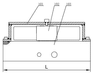
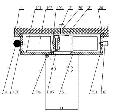
[0017] Such as figure 2 As shown, the present invention includes a box body 101, a solenoid valve 102 and a valve block 103. The box body 101 is an inner flange made of a metal material resistant to seawater corrosion. The solenoid valve 102 is placed in the box body 101, the valve block 103 and the solenoid valve 102 are fixed by the first hexagon socket head screw 105, the valve block 103 and the box body 101 are fixed by the countersunk head screw 5, and sealed by the fourth sealing ring 104 , the length of the valve block 103 is less than the length of the box body 101. The cover plate 3 and the box body 101 are fixedly connected through the second hexagonal screws 1 installed symmetrically, and form an installation cavity where the solenoid valve 102 can be installed. The connection between the box body 101 and the cover plate 3 is ...


PUM


Abstract

The invention relates to a split-type deep sea hydraulic valve box which comprises a box body, an electromagnetic valve and a valve block. The electromagnetic valve is arranged in the box body. The valve block is fixedly connected with the electromagnetic valve and the box body. A cover plate is connected with the box body and an installation containing cavity for installing the electromagnetic valve is formed. An air discharge screw is arranged on the cover plate. Two ends of the box body are further and respectively provided with a leather-bag type compensator and a watertight socket. According to sequential connection of the cover plate, the box body and the valve block, the installation containing cavity for installing the electromagnetic valve is formed. An existing connecting mode of a valve body and the box body is replaced by a connecting mode of the cover plate and the box body, so that the volume and the size of the valve body are further reduced and a technical index of a deep sea hydraulic system is satisfied. Meanwhile, according to the split-type deep sea hydraulic valve box, overhaul and repair of the electromagnetic valve can be completed just through detaching the screw and opening the cover plate, operation mode is simple and work efficiency is greatly improved.

Description

technical field [0001] The invention relates to deep-sea hydraulic equipment, in particular to a split-type deep-sea hydraulic valve box suitable for deep-sea ultra-high pressure environment. Background technique [0002] The hydraulic valve box is the key equipment in the deep sea hydraulic system. Its function is to distribute the pressure oil generated by the hydraulic source to each actuator and drive each actuator to move. Since it is a deep-sea operation, the equipment not only needs to have good seawater corrosion resistance, but also has a pressure compensation function to meet the requirements of survival in a deep-sea ultra-high pressure environment. [0003] The installation structure of the deep sea hydraulic valve box commonly used in the market is as follows: figure 1 As shown, it is composed of a box body 101, a solenoid valve 102 and a valve block 103. The box body 101 is an outer flange connected to the valve block 103 by fasteners. An installation cavity i...

Claims


Application Information

Patent Timeline
Patent Type & Authority Patents(China)
IPC IPC(8): F15B13/02
Inventor 邱中梁范华涛焦慧锋
Owner 中国船舶重工集团公司第七〇二研究所
Why Eureka
Try Eureka