Torque transmission device for a motor vehicle

A technology for motor vehicles and equipment, applied to mechanical equipment, mechanically driven clutches, non-mechanically driven clutches, etc., can solve the problem that the clutch is difficult to achieve fine and gradual manipulation, and achieve the effect of making up for invalid strokes and eliminating gaps

Active Publication Date: 2008-11-19
VALEO EMBRAYAGES SAS
View PDF5 Cites 0 Cited by
  • Summary
  • Abstract
  • Description
  • Claims
  • Application Information

AI Technical Summary

Problems solved by technology

Difficulty may be encountered at the start of actuation, however, because clutch actuation is not linear from a hydraulic pressure of zero due to eliminating backlash, lost travel, and stressing the equipment
Therefore, under the conditions described, it is difficult to achieve fine and gradual maneuvering when the clutch starts to actuate

Method used


Image

  • Torque transmission device for a motor vehicle
  • Torque transmission device for a motor vehicle
  • Torque transmission device for a motor vehicle

Examples


Embodiment Construction

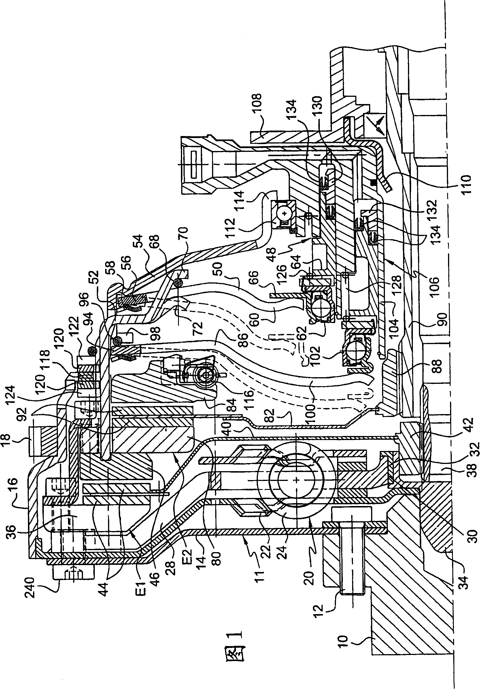
[0035] [35] First refer to FIG. 1, where reference numeral 10 denotes an end of a driving shaft, where the driving shaft is a crankshaft of an internal combustion engine of a motor vehicle, and a first inertia flywheel 11 is fixed on the crankshaft by screws 12. The first inertial flywheel 11 includes a flexible ring-shaped thin steel plate 14, its radially inner part is fixed on the shaft 10 by screws 12, and its radially outer part includes a cylindrical edge 16, which is opposite to the shaft 10. It extends in the direction and has a starting ring 18.

[0036] [36] The radially outer part of the annular thin plate 14 is connected to an input element of a torque buffer 20. This input element is formed by two parallel guide washers 22. The washers 22 include windows in which some coil springs 24 are located. Located in the circumferential direction around the rotating shaft 26 of the device, these springs cooperate with an output element 28 of the torque buffer. The output elemen...


PUM


Abstract

The invention relates to a torque transmission device, in particular for a motor vehicle, comprising at least one clutch (E1), arranged between a motor shaft (10) and an output shaft (38), operating means for the clutch (E1) with a hydraulic actuator (48), controlled by hydraulic fluid pressure and pressure compensation means, such as an annular diaphragm (50) on the clutch (E1), provided to act on the piston (64) of the hydraulic actuator (48) and prevent displacement thereof when the control pressure for the hydraulic actuator has not achieved a preset threshold value.

Description

Technical field [0001] [01] The present invention relates to a torque transmission device particularly for motor vehicles, said device comprising at least one mounted on a driving shaft and a driven shaft-the driven shaft is, for example, the input shaft of a gearbox- -Between the clutch, and the clutch actuation device, the actuation device includes a hydraulic cylinder (vérin hydraulique). Background technique [0002] [02] In a device of the type described, the actuating device of the clutch can be controlled by movement or pressure of hydraulic fluid. The pressure control is simpler, because only the hydraulic cylinder supply pressure needs to be adjusted to adjust the operation of the clutch, that is, to lock the clutch. However, difficulties may be encountered at the beginning of the actuation, because it is not linear to operate the clutch from a hydraulic pressure of one to zero due to the elimination of gaps, ineffective travel, and stress on the equipment. Therefore, un...

Claims


Application Information

Patent Timeline
IPC IPC(8): F16D25/08F16D21/06F16D25/10
CPCF16D2021/0669F16D2021/0607F16D21/06F16D25/087F16D25/10F16D2300/18
Inventor S·托米尔N·泰尔梅农P·泰里
Owner VALEO EMBRAYAGES SAS
Why Eureka
Try Eureka