
Stealth Air Conditioner with Wings for Electric Vehicles

A technology for electric vehicles and air conditioners, applied in air conditioning systems, space heating and ventilation, heating methods, etc., can solve problems such as increased manufacturing and use costs, rising system component costs, and inconvenient applications

Inactive Publication Date: 2016-12-14
孙善骏
View PDF7 Cites 0 Cited by
  • Summary
  • Abstract
  • Description
  • Claims
  • Application Information

AI Technical Summary

Problems solved by technology

[0002] At present, there is no such type of invisible air conditioner with wings attached to electric vehicles. The existing vehicle air conditioners only have a separate power drive mode in the car, which wastes a lot of energy and materials, and also increases manufacturing costs in other systems. and cost of use; the existing vehicle air conditioners and air ventilation adjustments are completely self-contained systems in the vehicle, resulting in low efficiency of the power system and increased cost of each system component; the existing vehicle air conditioners and air ventilation adjustments are also contradictory and inconvenient to apply In particular, electric vehicles have higher requirements for energy utilization efficiency, which often depends on whether they have a more efficient air-conditioning system. If the battery is used for cooling and heating alone, the mileage of electric vehicles will be reduced by about 60%. It is difficult to apply without refrigeration and heating. In order to improve this unfavorable situation, it is necessary to invent a suitable and advanced walking system that can cool and heat, float and charge cold and heat energy and electric energy, absorb and utilize external energy, and resolve resistance energy. The device, that is, the stealth air conditioner with wings for electric vehicles of the present invention

Method used


Image

  • Stealth Air Conditioner with Wings for Electric Vehicles

Examples


specific Embodiment approach

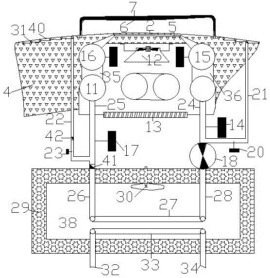
[0010] Specific implementation method: the lower attached wing conduit (5) is respectively connected to the control valve B (15) and the control valve C (16), and the control valve B (15) and the control valve C (16) respectively pass through the pipeline (35), The pipeline (36) is connected to both ends of the air-conditioning coil (11) in the car; the two ends of the air-conditioning coil (11) in the car are respectively connected to pipeline C (24) and pipeline D (25) and then respectively connected to the control valve On A(14) and control valve D(17), control valve A(14) and control valve D(17) respectively bypass control valve E(20) and control valve F(23) to form a circulation loop; The two ends of the coil (11) are connected to pipeline C (24) and pipeline D (25) respectively, and then respectively connected to control valve A (14) and control valve D (17), and control valve A (14) is connected to the pump ( 18), the pump (18) and the control valve D (17) are respectiv...


PUM


Abstract

The stealth air conditioner with attached wings for electric vehicles of the present invention mainly includes lower attached wings, lower attached wing conduits, upper attached wings, air conditioning coils in the car, pumps, heat storage and heat preservation balance boxes, heat absorbing pipes or heat absorbing runners in the compartment The lower wing and the upper wing form a certain angle and the air flows through it. The faster air speed between the lower wing and the upper wing will greatly reduce the temperature of the throat between the lower wing and the upper wing, and the cooling capacity will be input to the system device. Utilization, heat absorption pipes or heat absorption flow channels of the body can be arranged under the surface of other carriages outside the lower attached wing. External energy, solar energy, wind energy, etc. can be applied to the air conditioning and air ventilation conditioning system to resolve refrigeration during operation or at rest. The heat is reused by the vehicle air conditioner and air conditioning system, so as to obtain cooling and heating, float charge cold heat energy and electric energy, absorb and utilize external energy, and resolve resistance energy.

Description

technical field [0001] The invention relates to the field of motor vehicles, which is an invisible air conditioner with wings for electric vehicles that fully utilizes aerodynamic force, wind power and solar energy, and can convert air kinetic energy and solar energy into cooling and heating for vehicle air conditioners during the operation of the motor vehicle. The system installation scheme of air conditioning and reuse is suitable for various motor vehicles, especially for the application on electric vehicles. Background technique [0002] At present, there is no such type of invisible air conditioner with wings attached to electric vehicles. The existing vehicle air conditioners only have a separate power drive mode in the car, which wastes a lot of energy and materials, and also increases manufacturing costs in other systems. and use costs; the existing vehicle air conditioners and air ventilation adjustments are completely self-contained systems in the vehicle, resulti...

Claims


Application Information

Patent Timeline
Patent Type & Authority Patents(China)
IPC IPC(8): F24F5/00F24F11/02
Inventor 孙善骏
Owner 孙善骏
Learn More