
Axial and radial combined loading bearing test device

A composite loading and bearing test technology, applied in the direction of mechanical bearing testing, etc., can solve the problems of complex structure and operation procedures, difficulty in obtaining test bearing operation data, fluctuation of loading force, etc.

Active Publication Date: 2013-05-22
NO 510 INST THE FIFTH RES INST OFCHINA AEROSPAE SCI & TECH
View PDF5 Cites 21 Cited by
  • Summary
  • Abstract
  • Description
  • Claims
  • Application Information

AI Technical Summary

Problems solved by technology

[0003] Existing testing devices for rolling ball bearings often use elastic or rigid loading to carry out single axial or radial loading on the test bearing, and it is difficult to obtain the operating data of the test bearing under the combined action of axial load and radial load
The existing axial loading methods of rolling ball bearings often adopt methods such as pneumatic loading, spring leaf loading, rigid mechanism loading, etc., and a locking mechanism is set on the transmission shaft to load it. For a test with a long test time, such The loading method has large fluctuations in the loading force during the operation of the bearing, and it is not easy to observe. If a sensor is installed in the loading mechanism, it will complicate the design of the loading mechanism
For example, the patent publication number is CN200920311329.4, and the bearing load application device described in the patent named the load application device of the large-scale bearing testing machine adopts pneumatic loading in the axial and radial loading methods, and the loading structure involves the cylinder body, the piston Rods, guide sleeves, force sensors and other devices have complex structures and operating procedures, and the processing and manufacturing costs are relatively large

Method used


Image

  • Axial and radial combined loading bearing test device
  • Axial and radial combined loading bearing test device
  • Axial and radial combined loading bearing test device

Examples


Embodiment Construction

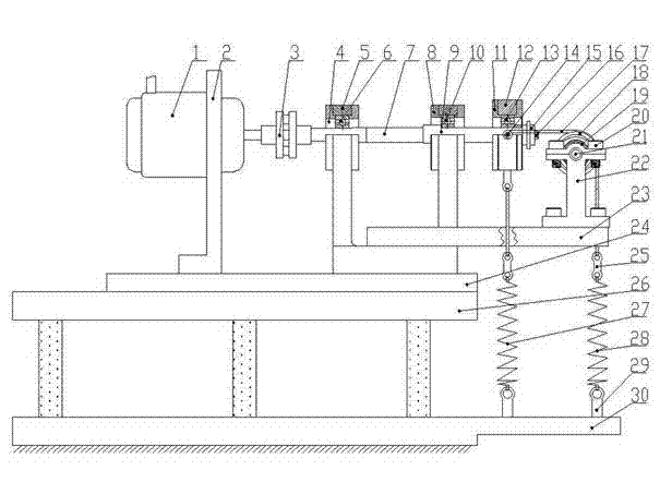
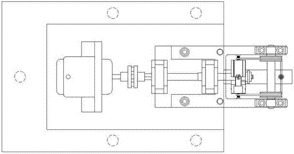
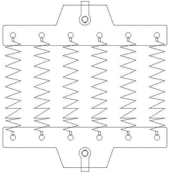
[0014] Such as figure 1 , figure 2 As shown, it is a front view and a top view of the axial and radial compound loaded bearing test device, which is the basic form of the present invention, which mainly consists of a motor 1, a motor support 2, a shaft coupling 3, a supporting bearing shoulder 4, a supporting bearing 5. Support bearing seat 6, main shaft 7, shaft step 9, test bearing 10, loading bearing outer casing 12, loading bearing 13, axial loading rod 14, shaft locking washer 15, axial locking nut 16, loading rope 17, fixed Pulley 18, radially loaded spring 27 and axially loaded spring 28 form. The test bearing 10 is under the action of the radial loading spring 27, the axial loading spring 28, the loading bearing 13 and the shaft step 9 respectively, and is loaded in both radial and axial directions at the same time, and is tested at a given speed of the motor 1 Under this condition, composite test conditions with different radial load, axial load and rotational spee...


PUM


Abstract

The invention discloses an axial and radial combined loading bearing test device. The axial and radial combined loading bearing test device comprises a motor, a motor stand, a main shaft, a supporting bearing, a bearing seat of the supporting bearing, a testing bearing, a loading bearing used for loading axial and radial force, a spring device used for loading radial force, and a spring device used for loading axial force. The loading bearing is arranged on the outer side of the testing bearing and the outer side of the supporting bearing, the bottom of a bearing sleeve of the loading bearing is connected with the spring device used for loading the radial force, and the spring device used for loading the radial force is arranged in the vertical direction. Axial loading rods are arranged on two sides of the middle of a bearing sleeve of the testing bearing and used for being connected with one end of a loading rope. The loading rope is wound around two fixed pulleys, and the other end of the loading rope is connected with the spring device used for loading the axial force. The axial and radial combined loading bearing test device is simple in structure, convenient to dismantle and install and easy to process and manufacture.

Description

technical field [0001] The invention relates to an axial and radial compound loaded bearing test device. Background technique [0002] In the actual transmission system, rolling ball bearings often operate under a certain load, which is mainly manifested in two aspects: axial load and radial load. In order to deeply study its operation process and performance under loads in different directions, it is very important to develop a test device that can apply axial load and radial load to the test bearing at the same time for the accurate and smooth development of the test test. [0003] Existing testing devices for rolling ball bearings often use elastic or rigid loading to carry out single axial or radial loading on the test bearing, and it is difficult to obtain the operating data of the test bearing under the combined action of axial load and radial load. The existing axial loading methods of rolling ball bearings often adopt methods such as pneumatic loading, spring leaf l...

Claims


Application Information

Patent Timeline
Patent Type & Authority Applications(China)
IPC IPC(8): G01M13/04
Inventor 胡继星周晖张凯锋桑瑞鹏郑玉刚张延帅
Owner NO 510 INST THE FIFTH RES INST OFCHINA AEROSPAE SCI & TECH
Learn More