
Radioactive aerosol sampling device

A sampling device and aerosol technology, which can be applied to sampling devices and other directions, can solve the problems of long sampling time, high cost of personnel evacuation, and large volume, and achieve the effects of improving sampling efficiency, shortening sampling time, and increasing sampling volume.

Active Publication Date: 2013-05-22
TSINGHUA UNIV
View PDF6 Cites 14 Cited by
  • Summary
  • Abstract
  • Description
  • Claims
  • Application Information

AI Technical Summary

Problems solved by technology

However, the following problems exist in the current radioactive environmental monitoring: after the accident, the accident area is highly radioactive, and it is not suitable for staff to enter to carry out ground sampling; the radioactive aerosol is distributed in a large area, and the cost of personnel evacuation is high
This kind of radioactive aerosol sampling device not only has a large volume, a long sampling time, and a small sampling coverage area, but also has certain restrictions on the sampling location due to the power supply requirements of the air extractor, so that the radioactive aerosol sampling device is only suitable for specific locations. sampling
[0004] Some air pollution observation samplers use aerial sampling, but their sampling tubes are perpendicular to the airflow direction and have corners, resulting in more aerosol loss and a small amount of aerosol collection, making it difficult to detect low activity levels

Method used


Image

  • Radioactive aerosol sampling device
  • Radioactive aerosol sampling device
  • Radioactive aerosol sampling device

Examples


Embodiment Construction

[0034] Embodiments of the present invention are described in detail below, examples of which are shown in the drawings, wherein the same or similar reference numerals designate the same or similar elements or elements having the same or similar functions throughout. The embodiments described below by referring to the figures are exemplary only for explaining the present invention and should not be construed as limiting the present invention.

[0035] In describing the present invention, it should be understood that the terms "center", "longitudinal", "transverse", "upper", "lower", "front", "rear", "left", "right", " The orientations or positional relationships indicated by "vertical", "horizontal", "top", "bottom", "inner" and "outer" are based on the orientations or positional relationships shown in the drawings, and are only for the convenience of describing the present invention and Simplified descriptions, rather than indicating or implying that the device or element refe...


PUM


Abstract

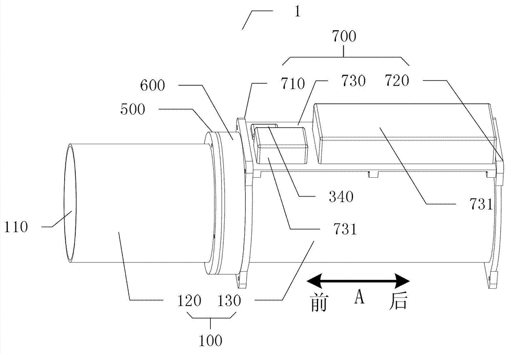
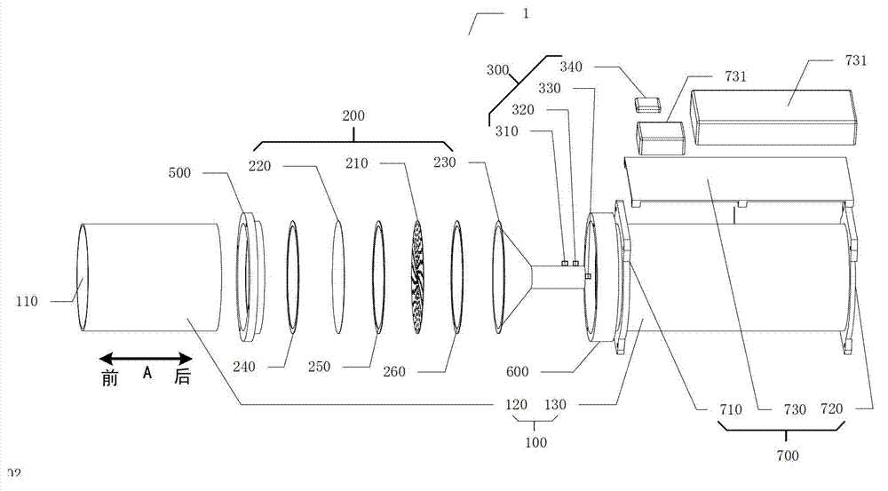
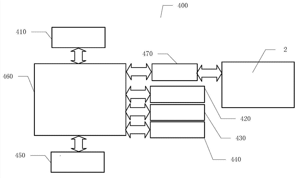
The invention discloses a radioactive aerosol sampling device, which is suitable to be fixed on an aircraft. The radioactive aerosol sampling device comprises a sampling tube, a sampling assembly, a detecting assembly, a processor assembly and a power supply, wherein a sampling cavity is arranged in the sampling tube; the sampling assembly is used for acquiring aerosol in air flowing through the sampling cavity; the detecting assembly comprises a temperature and humidity sensor, an air pressure sensor, a flow sensor and a GPS (global position system) antenna; the processor assembly is connected with the detecting assembly, and used for converting analog signals into digital signals and storing the digital signals; and the power supply is respectively connected with the processor assembly and the detecting assembly, and used for supplying power to the processor assembly and the detecting assembly. The radioactive aerosol sampling device disclosed by the embodiment of the invention has the advantages of small volume, short sampling time, wide sampling area, unrestricted sampling positions, large acquisition quantity, comprehensive data acquisition, and capability of improving the security of workers in accident areas, and the like.

Description

technical field [0001] The invention relates to the field of radioactive atmospheric environment monitoring, in particular to a radioactive aerosol sampling device. Background technique [0002] Radioactive aerosol monitoring is an important part of atmospheric environmental protection. It is of great significance for the timely detection of abnormal radioactive leakage in nuclear industry production and the implementation of atmospheric environmental pollution control. However, the current radioactive environmental monitoring has the following problems: after an accident, the accident area is highly radioactive, and it is not suitable for staff to enter to carry out ground sampling; the distribution of radioactive aerosols is large, and the cost of personnel evacuation is high. Therefore, how to carry out high-efficiency aerosol sampling in a large area under the premise of ensuring the safety of staff has become a problem in emergency monitoring of radioactive environments...

Claims


Application Information

Patent Timeline
IPC IPC(8): G01N1/22
Inventor 徐宏坤吴其反程建平
Owner TSINGHUA UNIV
Learn More