Card box lifting mechanism of card sender and card sender using the same

A technology of a card issuing machine and a lifting mechanism, which is applied in the field of card issuing machines, can solve the problems of complex mechanism and long time for assembling and disassembling the card box, and achieves the effects of reliable operation, simple structure, and firm assembly and disassembly.

Inactive Publication Date: 2015-03-04
GUANGDONG ELECTRONICS TECH RES INST
View PDF7 Cites 0 Cited by
  • Summary
  • Abstract
  • Description
  • Claims
  • Application Information

AI Technical Summary

Problems solved by technology

Regardless of any of the above-mentioned lifting methods, the card box needs to be flexibly driven to lift and stop at the frame, which will inevitably make the mechanism more complicated, and at the same time make the card box assembly and disassembly time too long

Method used


Image

  • Card box lifting mechanism of card sender and card sender using the same
  • Card box lifting mechanism of card sender and card sender using the same
  • Card box lifting mechanism of card sender and card sender using the same

Examples


Embodiment Construction

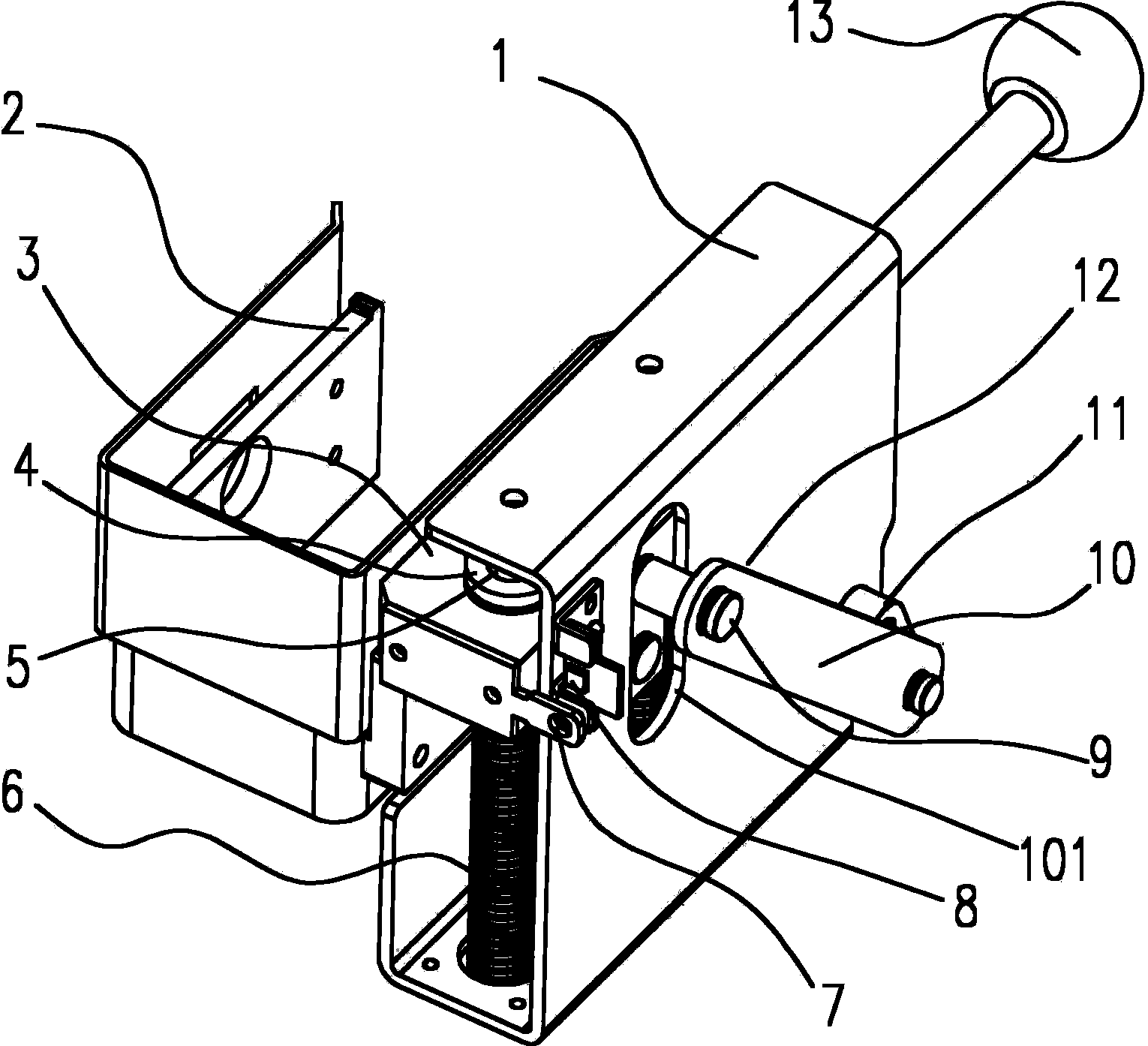
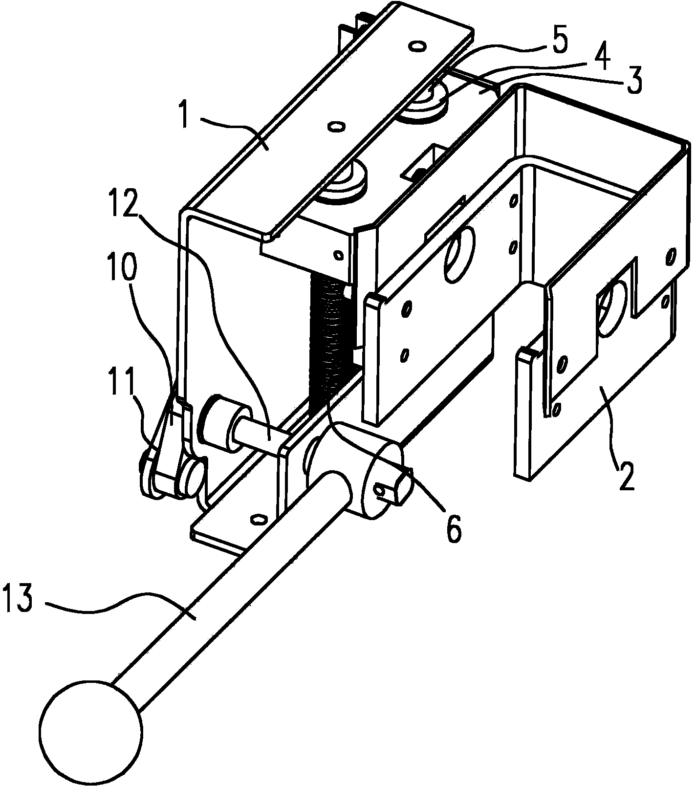
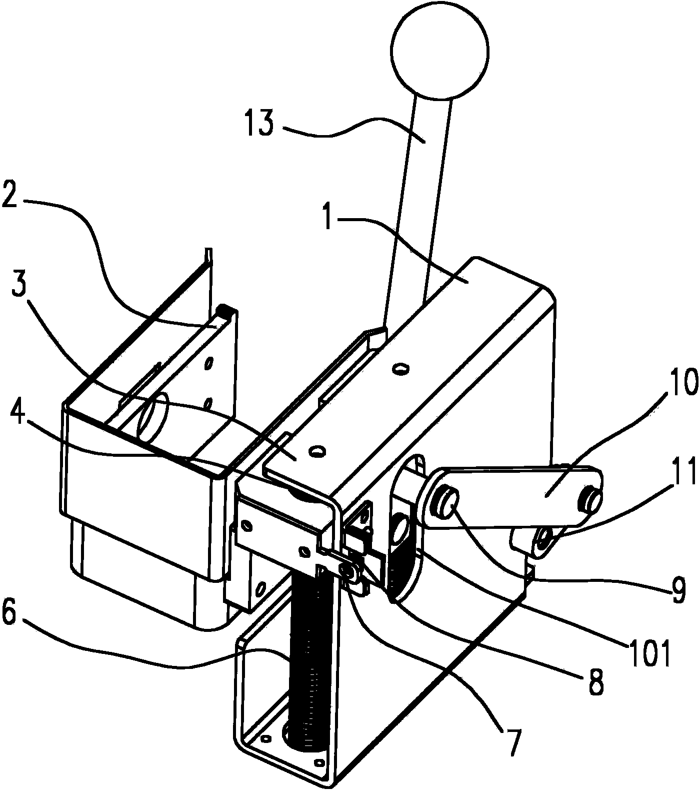
[0025] like Figures 1~4 The shown card box lifting mechanism of a card issuing machine includes a bracket 1, a slider 3, a guide column 5, a card box support plate 2 for supporting the card box 16, and a lifting mechanism for driving the slider to lift. The column 5 is vertically installed on the bracket 1, and the lifting mechanism is installed on the bracket 1 and has a start end for starting the lifting action and an output end for outputting the lifting action.

[0026] The lifting mechanism includes a handle rod 13, a crank 11, a connecting rod 10 and a connecting column 9. A conduction shaft 12 extends laterally from the end of the handle rod 13, and the conduction shaft 12 is hinged on the bracket 1; one end of the crank 11 is mounted on the On the conduction shaft 12, the other end of the crank 11 is hinged with one end of the connecting rod 10; the bracket 1 is provided with a chute 101 for the vertical sliding of the connecting column 9, and the rear end of the conn...


PUM


Abstract

The invention discloses a card box lifting mechanism of a card sender. The card box lifting mechanism comprises a support, a sliding block, a guide column, a card box supporting plate which is used for bearing a card box, and a lifting mechanism which is used for driving lifting of the sliding block, wherein the guide column is installed on the support in the vertical direction, the lifting mechanism is installed on the support and is provided with a starting end which is used for starting lifting motion and an output end which is used for outputting the lifting motion, the card box supporting plate is fixed on one side of the sliding block, the card box supporting plate is installed on the guide column in a sleeved mode and is matched with the guide column in a sliding mode, the output end of the lifting mechanism is connected with the sliding block, the starting end of the lifting mechanism is operated to enable the output end of the lifting mechanism to drive the sliding block to slide and lift on the guide column so as to drive the card box supporting plate to lift and lower the card box. The invention further discloses the card sender of the lifting mechanism. Lifting to assemble the card box or lowering to dismantle the card box is easily and conveniently achieved, and therefore storing cards inside the card box is convenient, the structure is simple, and work is reliable.

Description

technical field [0001] The invention relates to a card issuing machine, in particular to a card box lifting mechanism of the card issuing machine, and also relates to a card issuing machine using the mechanism. Background technique [0002] With the continuous increase in the mileage of expressways in my country, improving traffic efficiency and reducing operating costs have become the focus of expressway operators. The entrance lanes using unattended automatic card issuing machines can operate 24 hours a day without human intervention. , which reduces the operating cost of the charging unit, and has been widely used. [0003] The existing card issuing machines all include a chassis, a card box for holding cards, a card feeding mechanism for card feeding, a card dialing mechanism for card distribution, a card transmission mechanism for card transmission, and a card issuing mechanism for controlling the card issuance of the above institutions. control device. The card box ca...

Claims


Application Information

Patent Timeline
Patent Type & Authority Patents(China)
IPC IPC(8): G07B15/04
Inventor 徐青平翁名涛王德浩徐晓凡于晓丽陈丽珍唐箎
Owner GUANGDONG ELECTRONICS TECH RES INST
Why Eureka
Try Eureka