Rotor and permanent magnetic rotating machine

A permanent magnet, rotating machine technology, applied in the magnetic circuit shape/style/structure, magnetic circuit, motor and other directions, can solve problems such as motor output deterioration, and achieve the effect of high anti-demagnetization and high output characteristics

Active Publication Date: 2013-05-22
SHIN ETSU CHEM CO LTD
View PDF8 Cites 12 Cited by
  • Summary
  • Abstract
  • Description
  • Claims
  • Application Information

AI Technical Summary

Problems solved by technology

As a result, when a magnet with an excessively strong coercive force is used in a rotating machine, there is a problem that the output of the motor deteriorates

Method used


Image

  • Rotor and permanent magnetic rotating machine
  • Rotor and permanent magnetic rotating machine
  • Rotor and permanent magnetic rotating machine

Examples


Embodiment 1

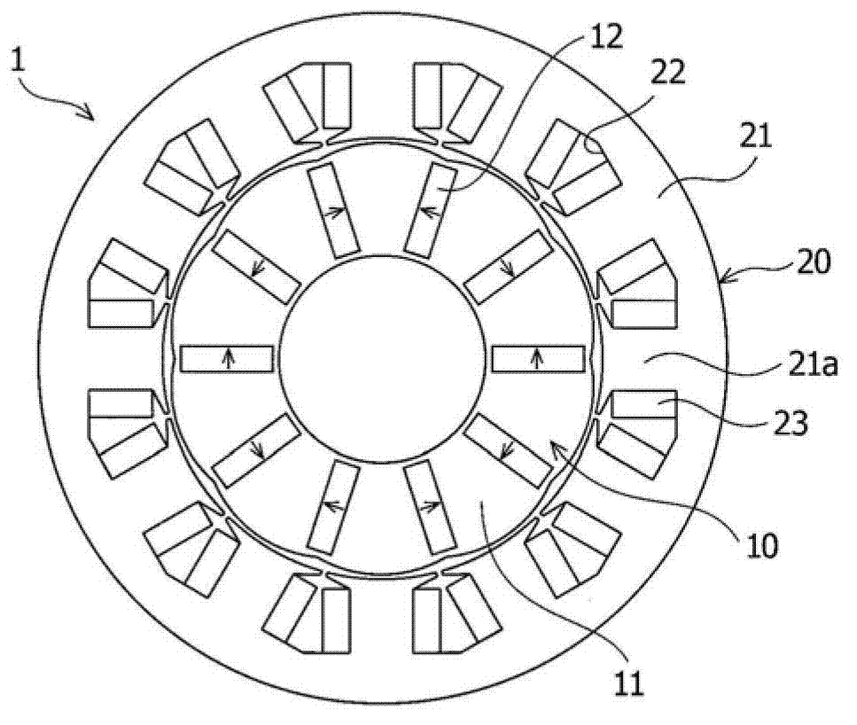
[0045] As the magnet, a rectangular parallelepiped Nd-based rare earth sintered magnet Nd 2 Fe 14 B, wherein the residual magnetic flux density is 1.32T, the coercive force is 1000kA / m, the size is 12mm length×3mm width×50mm height, and the width direction is the magnetization direction. Two or more magnets are provided and diffused. As diffusion, granular dysprosium fluoride having an average particle diameter of 5 μm was mixed with ethanol at a weight ratio of 1:1, the magnet was immersed in the mixture, and thereafter, heat treatment was performed at 900° C. for 1 hour in an Ar atmosphere. For one of the diffused magnets, a cube of 1 mm on each side was cut from the corner containing the vertices of the magnet and the coercivity was determined by using a BH tracer. As a result, the coercive force of the magnets at the corners was 1600 kA / m. Therefore, the coercivity increases by 600 kA / m.

[0046] like figure 1 As shown, the magnets were installed in a rotating machine...


PUM


Abstract

Disclosed are a rotor adapted for a permanent magnetic rotating machine and the permanent magnetic rotating machine having a high output and demagnetization resistance. Provided are a rotor adapted for a permanent magnetic rotating machine, the machine comprising a rotor and a stator comprising a stator core having two or more slots, and winding wires wound through the stator core, the rotor comprising: a rotor core having two or more insertion holes formed in the rotor core; and two or more permanent magnets in the two or more insertion holes; and each of the permanent magnets is in form of rectangle with two opposite sides substantially parallel to a radial direction of the rotor on a surface vertical to a rotation axis of the rotor, and is in form of rectangular parallelepiped with four longitudinal edges parallel to the rotation axis, and the permanent magnet has at least one angular portion of four angular portions containing the four longitudinal edges, which has stronger coercive force than a center within the rectangular parallelepiped, and is placed in the insertion hole in such a manner that one of the at least one angular portion is in a stator side and in the rear of a rotating direction of the rotor, and a permanent magnetic rotating machine comprising the rotor.

Description

technical field [0001] The present invention relates to a rotor used in a permanent magnet type rotating machine and a permanent magnet type rotating machine including the rotor. A permanent magnet type rotating machine (so-called in-place permanent magnet (IPM) rotating machine) includes a rotor with two or more permanent magnets in a rotor core, and a stator with a gap arrangement from the rotor and with two or more permanent magnets. A stator core of a plurality of slots and winding wires wound around the stator core. Background technique [0002] Due to the excellent magnetic properties, Nd-based sintered magnets are being used more and more widely. In recent years, even in the field of rotating machines such as electric motors or generators, permanent magnet type rotating machines using Nd-based sintered magnets have been developed for the purpose of being thin and compact, high performance, and energy saving of equipment. In particular, since an IPM rotating machine ...

Claims


Application Information

Patent Timeline
Patent Type & Authority Applications(China)
IPC IPC(8): H02K1/27
CPCH02K1/27H02K1/02Y02T10/641H02K1/2773H02K2213/03
Inventor 小林秀树
Owner SHIN ETSU CHEM CO LTD
Why Eureka
Try Eureka