Wave crest nozzle installation structure

A mounting structure and nozzle technology, which is applied in the direction of assembling printed circuits with electrical components, can solve problems affecting the placement of components, etc.

Inactive Publication Date: 2013-05-22
XIAN ZHONGKEMAITE ELECTRONICS TECH EQUIP
View PDF0 Cites 3 Cited by
  • Summary
  • Abstract
  • Description
  • Claims
  • Application Information

AI Technical Summary

Problems solved by technology

[0002] With the development of electronic products, according to the requirements of various functions, the requirements for the soldering position of the components on the PCB are getting higher and higher. There are all through-hole plug-in PCBs, all patch PCBs, and plug-in mixed PCBs. The current The process is that all through-hole plug-in PCBs are soldered with a wave soldering machine; all patch PCBs are soldered with a reflow soldering machine; there are two types of plug-in mixed PCBs, and the plug-in mixed components on the same side of the PCB are first soldered with a reflow soldering machine Mount the components, and then solder the plug-in components with a wave soldering machine; if the plug-in mixed components are not on the same side of the PCB, first use the reflow soldering machine to solder the mounted components, and then manually solder the plug-in components, because if you use a wave soldering machine to solder the plug-in components Mounted components will affect soldered mounted components

Method used


Image

  • Wave crest nozzle installation structure

Examples


Embodiment Construction

[0008] The present invention will be described in further detail below in conjunction with the accompanying drawings and embodiments.

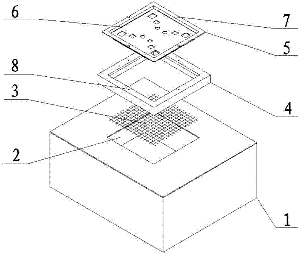
[0009] As shown in the accompanying drawings, the present invention is a mounting structure for a wave crest nozzle, including a nozzle retaining frame 4, which is fixedly welded at the opening 2 of the tin furnace, so that the wave crest gushes out in a shape surrounded by the nozzle retaining frame 4, and the The net 3 is installed on the bottom of the nozzle retaining frame 4 to make the wave crest evenly emerge. There is an opening on the nozzle 5, which corresponds to the position of the PCB board to be soldered. It is in close contact with the inner edge of the nozzle baffle frame 4, and the spout 5 is extended through the fastening screw 7 and the threaded hole 8 on the nozzle baffle 4 to be fastened and installed.

[0010] In this way, when the crest generator is working, the entire crest emerges from the opening 2 of the tin furnace, ...


PUM


Abstract

The invention relates to a wave crest nozzle installation structure comprising a nozzle stopping frame, wherein the nozzle stopping frame is fixedly welded on an opening of a solder machine to enable a wave crest to gush in a shape which is surrounded by the nozzle stopping frame, a separating net is installed at the bottom of the nozzle stopping frame to enable the wave crest to gush evenly, holes is formed in a nozzle, the position of the holes corresponds to that of a printed circuit board (PCB) needing to be welded, reflux grooves are formed in the periphery of the interior of the nozzle, the edge of the concave part of the nozzle is tightly attached to the inner edge of the nozzle stopping frame, and the extension of the nozzle is installed in a fastening mode through fastening screws and threaded holes in a nozzle flapper. So that, after a wave crest generator works, the whole wave crest gushes from the opening of the solder machine, evenly gushes upwards to the nozzle from the rectangular area surrounded by the nozzle stopping frame, and gushes out of the holes of the nozzle, the PCB is welded selectively, gushed liquid-state tin further flows toward the solder machine through the reflux grooves, and the whole welding process is completed. The wave crest nozzle installation structure is simple in structure, and high in weld efficiency, and the nozzle is easy to replace.

Description

technical field [0001] The invention belongs to the field of selective wave soldering equipment, and more specifically provides a wave nozzle installation structure. Background technique [0002] With the development of electronic products, according to the requirements of various functions, the requirements for the soldering position of the components on the PCB are getting higher and higher. There are all through-hole plug-in PCBs, all patch PCBs, and plug-in mixed PCBs. The current The process is that all through-hole plug-in PCBs are soldered with a wave soldering machine; all patch PCBs are soldered with a reflow soldering machine; there are two types of plug-in mixed PCBs, and the plug-in mixed components on the same side of the PCB are first soldered with a reflow soldering machine Mount the components, and then solder the plug-in components with a wave soldering machine; if the plug-in mixed components are not on the same side of the PCB, first use the reflow solderi...

Claims


Application Information

Patent Timeline
IPC IPC(8): H05K3/34
Inventor 何锐梁保华
Owner XIAN ZHONGKEMAITE ELECTRONICS TECH EQUIP
Why Eureka
Try Eureka