Heat exchanger perforated fins

A plate-fin heat exchanger and fin technology, applied in the direction of indirect heat exchangers, heat exchanger types, heat transfer modification, etc., can solve the problems of not providing guidance, not showing perforation, etc., to reduce capital and Operating cost, overall capital and operating cost reduction, effect of reduced pressure drop loss

Inactive Publication Date: 2013-05-22
AIR PROD & CHEM INC
View PDF5 Cites 11 Cited by
  • Summary
  • Abstract
  • Description
  • Claims
  • Application Information

AI Technical Summary

Problems solved by technology

Figure 2 of the Hendrix patent shows that the perforations are a single row of perforations along the side of the fin 21, however, the perforations are not shown on t

Method used


Image

  • Heat exchanger perforated fins
  • Heat exchanger perforated fins
  • Heat exchanger perforated fins

Examples


example 1

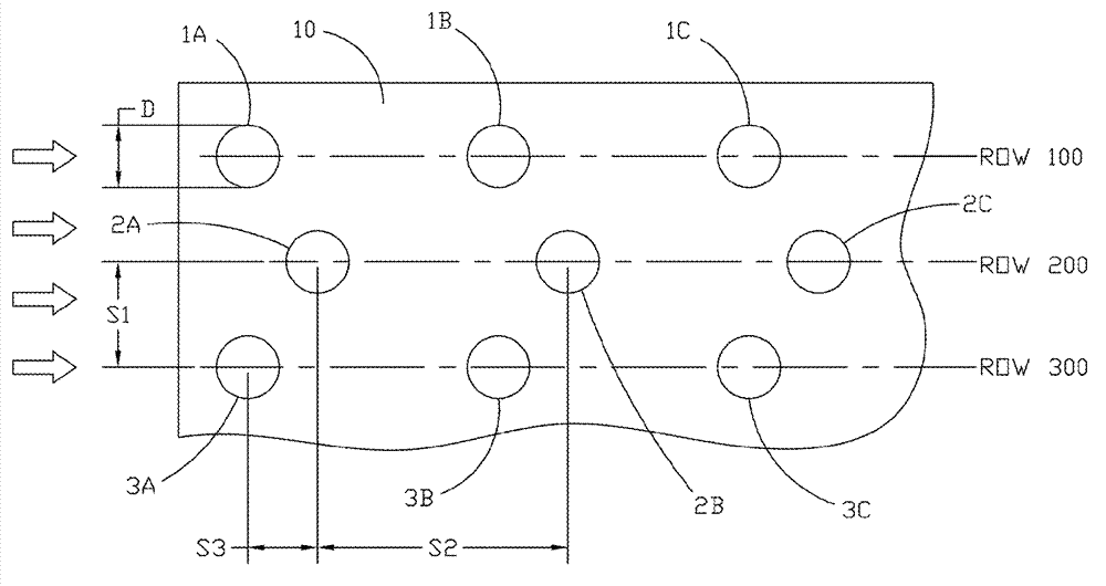
[0043] To better understand the effect of perforations within the fin geometry, several sample problems were solved using computer fluid dynamics (CFD). When using this technique, the computation is usually constrained to some repetitive structure in order to limit the computational size of the problem. However, the overall geometry of the heat exchanger is very complex when we try to quantify the effect of a specific perforation pattern, even when we restrict the problem to a single subchannel within the plate-fin passage. For this reason, different types of approximations are used.

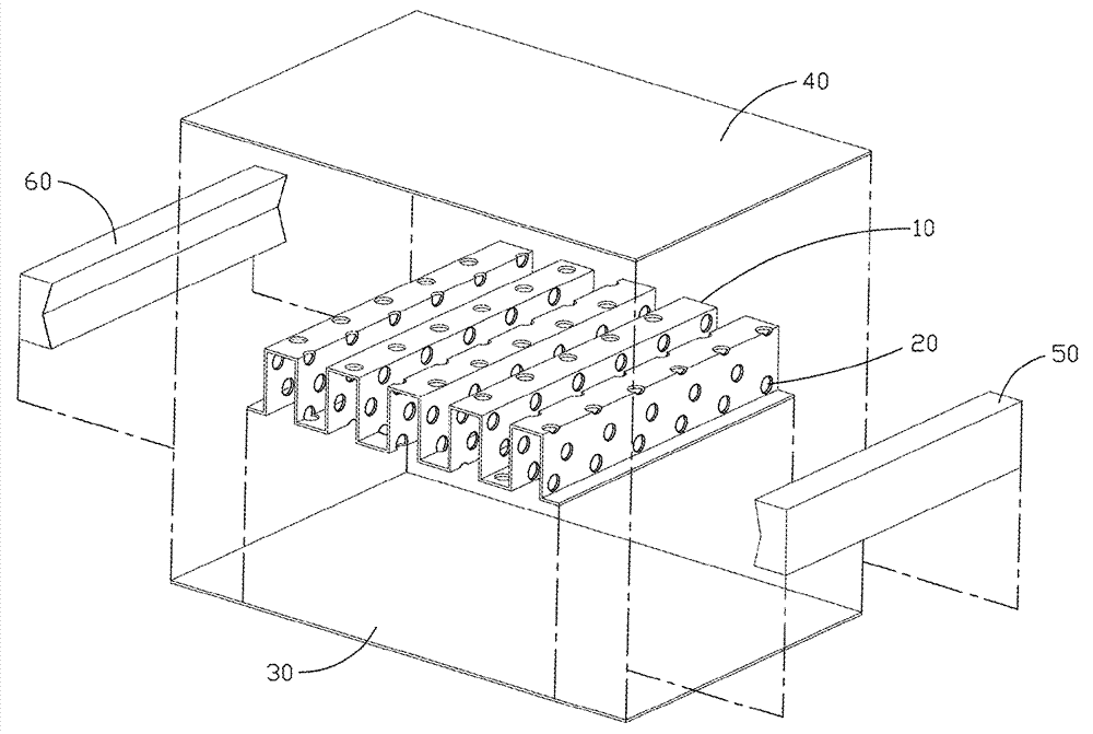
[0044]In most plate-fin exchangers, the secondary surface area tends to be the majority of the total area. As noted above, this is the area represented by the fin legs spanning and separating the divider plates or plates 30, 40 representing the major surface area. To understand the effect of the positioning of the perforations, a typical periodic area of ​​two infinite parallel plates was mode...


PUM

PropertyMeasurementUnit
Perforation diameteraaaaaaaaaa

Abstract

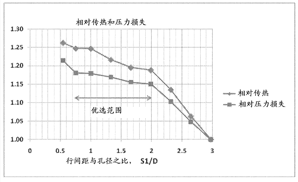
A plate fin heat exchanger comprises a folded fin sheet comprising fins wherein the fin sheet comprises a plurality of perforations, such plurality of perforations are positioned on the fin sheet in parallel rows when such fin sheet is in an unfolded state, such parallel rows of perforations on the fin sheet comprise a first spacing between the parallel rows of perforations (S1), a second spacing between sequential perforations within the parallel row of perforations (S2), a third spacing (or offset) between the perforations in adjacent parallel rows of perforations (S3), and a perforation diameter (D), wherein the ratio of the first spacing between the parallel rows of perforations to the perforation diameter (S1/D) is in the range of 0.75 to 2.0, and wherein the angle between the fins and the parallel rows of perforations is less than or equal to five degrees (= 5 DEG ).

Description

Background technique [0001] The plate -winged heat exchanger is generally used to change heat between the flow of heating, cooling, boiling, evaporation or condensation process flow.The process conditions in these heat exchangers may include single or two -phase flow and heat transfer.Although some plate -winged switches contain only two streams, others include multiple streams in multiple groups of wings.Solid flows can be used to recover with the heat exchanger with a sprayer and a collector to recover from the heat exchanger.Each stream flows into the specific plate wings in the adjacent plate wing channel.The separate plate wing path is included between multiple pairs of partitions. These partitions are separated by the wing tablets and the plate wing channels are wrapped on the periphery. ThereforeInterested fluid.When flowing at different temperatures in different temperatures of each other, they are separated by the separators called the main heat -up surface and the winged...

Claims


Application Information

Patent Timeline
IPC IPC(8): F28D9/00F28F3/02
CPCF25J5/00F25J5/002F28F13/18B21D53/04B21D53/022F28D9/0062F25J2290/12F28F3/027F28F3/08Y10T29/49366F28D9/00F28F3/02
Inventor S.森德V.Y.格尔什泰因G.A.梅斯基P.A.霍顿
Owner AIR PROD & CHEM INC
Why Eureka
Try Eureka