
exposure system

An exposure system and polarizer technology, applied in the field of exposure systems, can solve the problems of irregular polarization patterns, low efficiency, and uneven exposure in the exposure area, and achieve uniform and accurate polarization pattern formation, minimized light loss, and uniform exposure and the effect of pattern formation

Active Publication Date: 2016-02-17
DONGWOO FINE CHEM CO LTD
View PDF8 Cites 0 Cited by
  • Summary
  • Abstract
  • Description
  • Claims
  • Application Information

AI Technical Summary

Problems solved by technology

[0004] The current exposure system, such as that disclosed in Korean Laid-Open Patent Publication No. 2003-40674, has the disadvantage of low efficiency because it is not suitable for continuous processes or the exposure area of ​​the mask is narrow.
[0005] Also, if the exposure area is a curved surface, the amount of exposure that reaches the exposure area through the mask becomes uneven, which is considered to be the cause of the irregularity of the polarization pattern, so it is considered necessary to keep the exposure area flat

Method used


Image

  • exposure system
  • exposure system
  • exposure system

Examples


Embodiment Construction

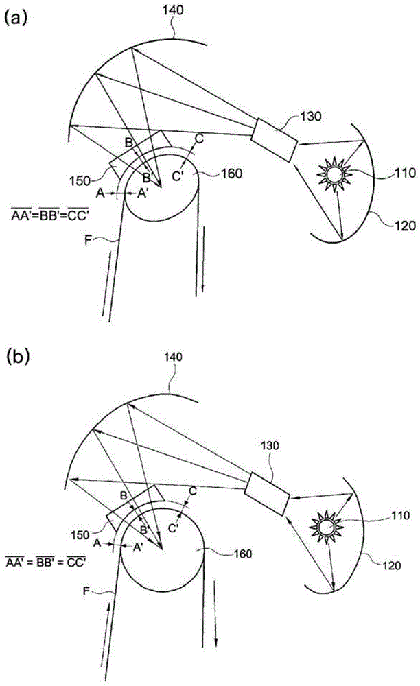
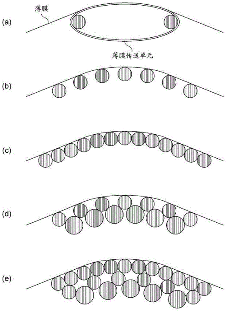
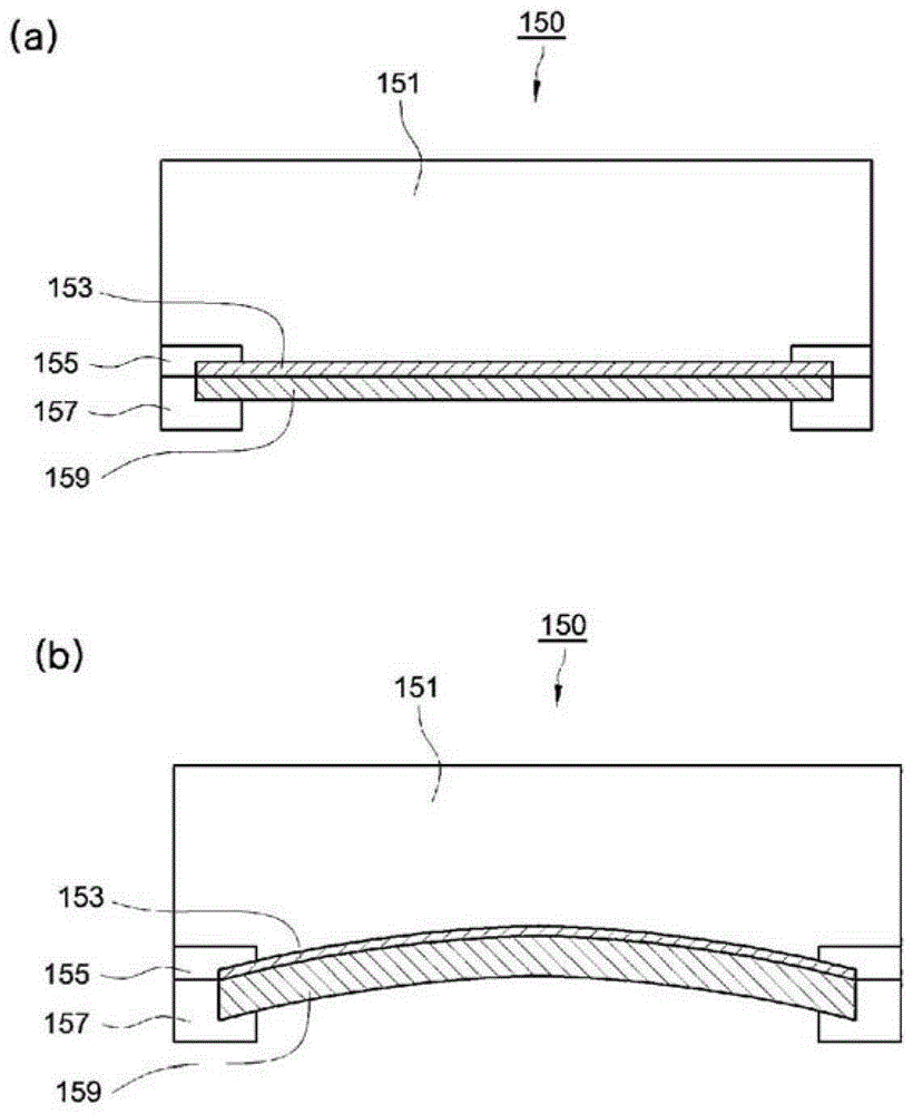
[0041] The exposure system involved in the present invention includes: a light-emitting unit; a film transfer unit, the film is attached to its surface, and is bent into a circle, an ellipse or a state with partial curvature to be transported; and a pattern forming unit, which transmits the light emitted by the above-mentioned light-emitting unit The above-mentioned film bonded to the above-mentioned film, and form a polarizing pattern on the above-mentioned film, thereby, in the case of continuously unwinding the film wound on the roller and forming a polarizing pattern, the vibration and bending of the film can also be minimized, and the Uniform exposure over a wider area contributes to the improvement of the quality of pattern retarders, etc. and the improvement of production efficiency.

[0042] The present invention will be described in detail below.

[0043] The exposure system of the present invention, for example figure 1 composition shown. figure 1 The exposure syst...


PUM


Abstract

The present invention relates to a light-exposure system, and more specifically relates to a light-exposure system comprising: a light-emitting unit; a film-conveying unit wherein a film makes close contact with the surface thereof and is conveyed while being bent into a circle, an ellipse or the curvature of part thereof; and a pattern-forming unit for forming a polarisation pattern on the film by transmitting, onto the closely contacting film, the light emanating from the light-emitting unit. As a result, the light-exposure system is able to minimise film jittering and weaving even when formation of the polarisation pattern is carried out while the film, which is wound on a roller, is continuously played out, and allows uniform light exposure over a relatively wide region such that the invention is able to contribute to improved quality, notably in the patterned retarder, and increased production efficiency.

Description

technical field [0001] The invention relates to an exposure system for continuously forming polarized light patterns. Background technique [0002] The exposure system continuously unwinds the film wound on the reel, and after coating and drying the unwound portion, irradiates light to form a polarized pattern. During the process of unwinding and moving the film by the exposure system, the bending and shaking of the film will occur, which will be the main cause of the irregularity of the polarization pattern formed in the film. [0003] A thin film with an irregular polarizing pattern lowers the polarizing performance, and causes a problem that the performance of a 3D display to which the thin film is attached also significantly deteriorates. Therefore, it is necessary to search for a method for regularly forming an exposure pattern on a thin film. [0004] Current exposure systems such as those disclosed in Korean Laid-Open Patent Publication No. 2003-40674 have disadvant...

Claims


Application Information

Patent Timeline
Patent Type & Authority Patents(China)
IPC IPC(8): G03F7/20G03F9/00G02F1/00
CPCG03B1/46G03B27/04G03F7/24
Inventor 崔凤珍金龙焕
Owner DONGWOO FINE CHEM CO LTD
Learn More