Blowing round roller extraction cutter

A round roller and knife body technology, applied in the field of extraction knives, can solve the problems affecting the yield and production efficiency of die-cut products, and achieve the effect of preventing accumulation and improving yield and production efficiency

Inactive Publication Date: 2013-06-05
SUZHOU YUANDEFU TECH
View PDF5 Cites 2 Cited by
  • Summary
  • Abstract
  • Description
  • Claims
  • Application Information

AI Technical Summary

Problems solved by technology

In the subsequent production process, the deformed protrusion on the surface of the extraction knife wi

Method used


Image

  • Blowing round roller extraction cutter
  • Blowing round roller extraction cutter
  • Blowing round roller extraction cutter

Examples


Example Embodiment

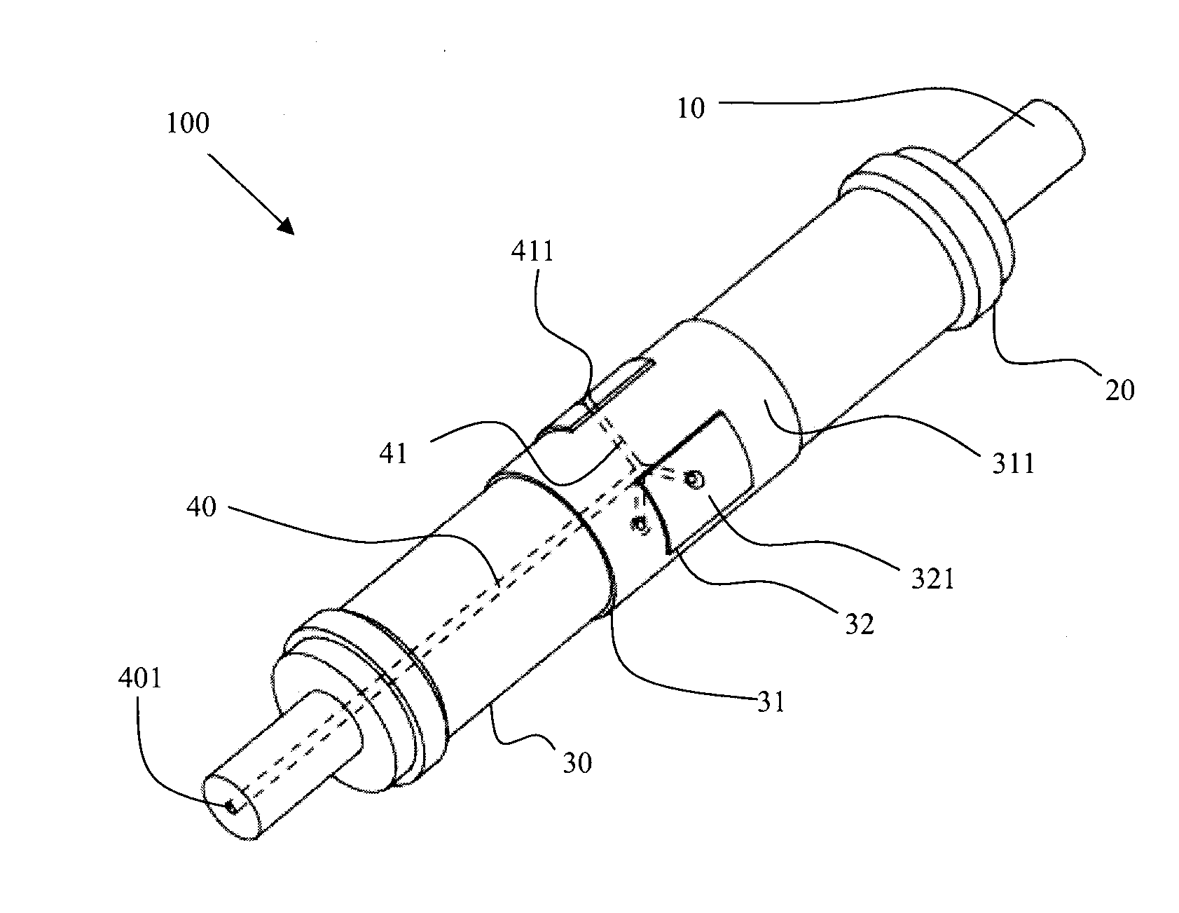
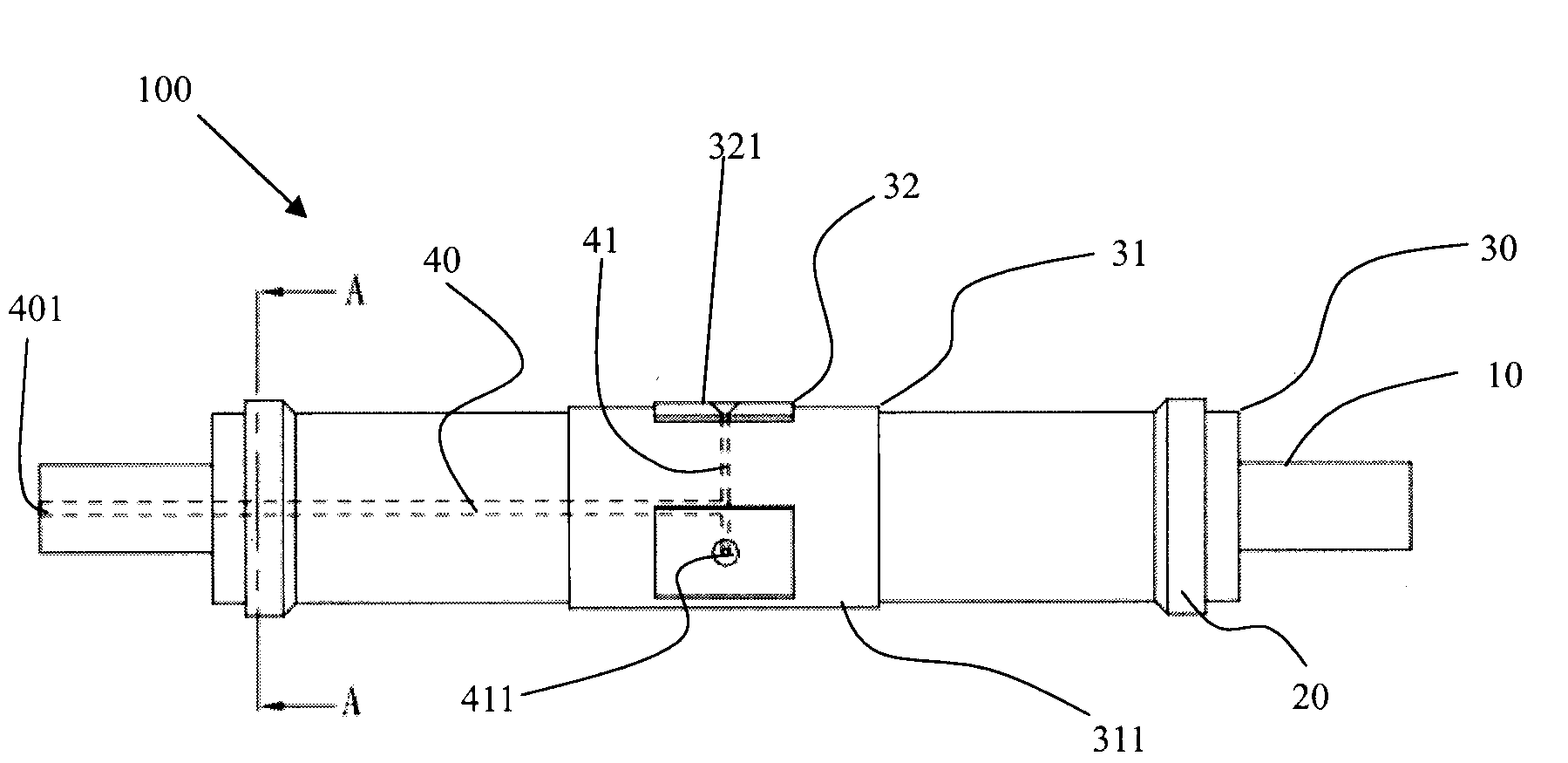
[0017] The present invention will be described in detail below in conjunction with the embodiments shown in the drawings. However, these embodiments do not limit the structural or functional changes made by those skilled in the art based on these embodiments to be included in the protection scope of the present invention. The following embodiments will take an air blowing round roller extraction knife with three rectangular units as an example to describe the present invention, but the application of the present invention is not limited to the air blowing round roller extraction knife with three rectangular units. It can also be applied to other blowing round roller extraction knives with complex graphics or different unit numbers.

[0018] Participate Figure 1 to Figure 2 A specific embodiment of a blowing round roller extraction knife of the present invention is shown. In this embodiment, an air blowing round roller extraction knife 100 includes: a main shaft 10, and a cutter...


PUM


Abstract

The invention provides a blowing round roller extraction cutter which comprises a main shaft, a cutter body connected with the main shaft, positioning blocks which are located on the same axis with the main shaft and arranged on the end portions of the two ends of the cutter body, a first protruding stretch part which stretches out of the surface of the cutter body in a protruding mode, and a second protruding stretch part which stretches out of the surface of the first protruding stretch part in a protruding mode. A plurality of auxiliary channels are arranged inside the cutter body, a main channel arranged in a shaft center of the main shaft is arranged inside the cutter body, and the auxiliary channels are mutually communicated with the main shaft. Compressed air is guided into the main channel on the end portion of the main shaft, the extraction cutter is enabled to blow away waste materials by utilization of the compressed air in a waste material ejection process, the waste materials are prevented from being adhered to the protruding stretch parts of the extraction cutter and stacking, the waste material removing effect is improved, and the finished product rate and the production efficiency of a die cutting product are improved.

Description

technical field [0001] The present invention relates to an extraction knife, and more particularly to an extraction knife with an air-blowing round roller that removes die-cutting waste by using a protruding portion on the surface of a knife body during the process of manufacturing a die-cut product. Background technique [0002] Die-cut products generally consist of a release liner, a protective layer and an adhesive layer in between. Die-cut products are widely used in automobile manufacturing, electronics industry, especially flat panel display, mobile digital industry. According to the shape of the internal frame of the electronic product, use a die-cutting knife with a specific shape to stamp or roll to die-cut a specific shape. Then peel off the protective layer on the surface, stick the die-cut product on the inner frame of the electronic product, then peel off the release paper, and finally fix the inner frame and outer shell of the electronic product firmly with th...

Claims


Application Information

Patent Timeline
IPC IPC(8): B26D7/18
Inventor 张明
Owner SUZHOU YUANDEFU TECH
Why Eureka
Try Eureka