Dyeing rack for tatting yarn, zippers, ropes, ribbons and loose fibers of loading needles of dyeing machine

A technology of dyeing machine and loose fiber, applied in the field of dyeing machine

Inactive Publication Date: 2013-06-05
GUANGZHOU GAOSHENG DYEING & FINISHING EQUIPCO
View PDF5 Cites 19 Cited by
  • Summary
  • Abstract
  • Description
  • Claims
  • Application Information

AI Technical Summary

Problems solved by technology

[0003](1) The spindles of the package yarn dyeing machine are usually mounted on the pull rod of the creel. The traditional stacking spindle device is backward and inconvenient for installation and unloading, especially because the staff fall down at high temperature or extend their arms to extend their body because the length of the arm of the tie rod is exceeded, which makes the staff easy to be injured during the operation of installing the spindle. The height is generally 2-5 meters high, and manual loading is usually impractical and time-consuming
[0004](2) The flow resistance of the dyeing liquid is large. The traditional yarn rod is a water outlet hole with a yarn rod sleeve installed in the yarn rod barrel. Due to the resistance generated by the sleeve, the dyeing The liquid does not flow smoothly through the outlet hole, which affects the pump speed and causes power loss of the motor
[0006](4) Large liquor ratio
The spindles of the traditional sarong are dyed in the state of being soaked and saturated with water. Since the sarong is soaked in the dyeing solution, the resistance of the sarong increases due to the dyeing water.

Method used


Image

  • Dyeing rack for tatting yarn, zippers, ropes, ribbons and loose fibers of loading needles of dyeing machine
  • Dyeing rack for tatting yarn, zippers, ropes, ribbons and loose fibers of loading needles of dyeing machine
  • Dyeing rack for tatting yarn, zippers, ropes, ribbons and loose fibers of loading needles of dyeing machine

Examples


Embodiment Construction

[0035] The specific implementation of the present invention will be further described below in conjunction with the accompanying drawings, but the implementation and protection scope of the present invention are not limited thereto.

[0036] The dyeing rack of the present invention can be loaded with needle weaving yarn, zippers, ropes, tapes or loose fibres.

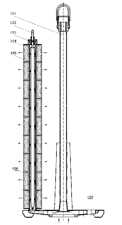
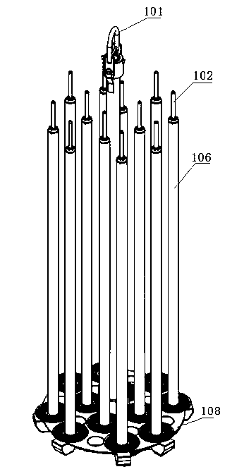
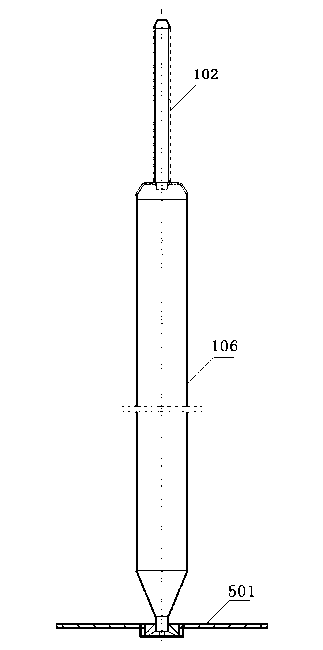
[0037] Such as Figure 1 ~ Figure 4 , the dyeing frame includes a yarn disc 108, a suspender 101 and a yarn rod 106; the upper surface of the yarn disc 108 is disc-shaped, and the lower end of the yarn disc is a cavity structure, and the bottom of the lower end of the yarn disc is connected with the central seat of the yarn dyeing machine, and the upper surface of the yarn disc is The surface is provided with the water outlet hole of the yarn tray, the return hole of the yarn tray and the hole seat of the boom. The hole seat of the boom is set on the center of the yarn tray, and the boom is fixedly installed in the hole...


PUM


Abstract

The invention discloses a dyeing rack for tatting yarn, zippers, ropes, ribbons and loose fibers of loading needles of a dyeing machine. The dyeing rack for tatting the yarn, the zippers, the ropes, the ribbons and the loose fibers of the loading needles of the dyeing machine comprises a yarn plate, a suspender and a yarn rod. The upper surface of the yarn plate is in a disc shape. The lower end of the yarn plate is in a cavity structure. A center seat of the dyeing machine is connected with the bottom of the lower end of the yarn plate. A yarn plate water outlet, a yarn plate water return hole and a suspender hole seat are formed in the upper surface of the yarn plate. The suspender hole seat is arranged at the center of the yarn plate. A suspender is fixedly installed in the suspender hole seat. The bottom of the yarn rod is fixed on the yarn plate water outlet of the upper surface of the yarn plate. The yarn rod is in a solid structure or a hollow structure. A gap is reserved between a to-be-dyed object and the yarn rod. Dye liquor flows out of the yarn plate water outlet hole of the bottom of the yarn rod and fills the gap to form a hollow water column. The dye liquor permeates the to-be-dyed object through flowing of the hollow water column. The dye liquor permeated from the to-be-dyed object flows into the yarn plate water return hole. A bolt at the upper end of the yarn rod is provided with a gravity tapered end. The dyeing rack for tatting the yarn, the zippers, the ropes, the ribbons and the loose fibers of the loading needles of the dyeing machine is simple in structure, capable of reducing consumption of dye, auxiliaries, energy sources and water resources, and capable of improving dyeing efficiency.

Description

technical field [0001] The invention relates to the technical field of dyeing machines, in particular to a dyeing rack loaded with needle-woven yarns, zippers, ropes, belts and loose fibers. Background technique [0002] Traditional cheese dyeing machine sarongs, also known as cheese creels (dyeing racks), such as high-temperature and high-pressure cheese dyeing machine creels, can be used for dyeing cheese spindles suitable for various chemical fibers and blended spinning, especially for cotton, polyester cotton, etc. The variety of spindle dyeing, but the creel of the traditional cheese dyeing machine has the following problems: [0003] (1) The spindles of cheese dyeing machines are usually loaded on the rods of the creel. The spindles are usually stacked and locked on the spindle rods by the yarn rods. The old traditional stacked spindles are backward, which is not easy to install and unload, especially because Workers fall down at high temperature or extend their arms ...

Claims


Application Information

Patent Timeline
Patent Type & Authority Applications(China)
IPC IPC(8): D06B23/04
CPCD06B5/16
Inventor 萧振林钟汉如王江民陆强
Owner GUANGZHOU GAOSHENG DYEING & FINISHING EQUIPCO
Why Eureka
Try Eureka