
Low carbon and energy-saving gas heat treatment tunnel kiln

A tunnel furnace and gas technology, which is applied in the field of heat treatment, can solve the problems of low combustion temperature and low fuel combustion rate, and achieve the effect of saving gas supply

Inactive Publication Date: 2013-06-05
INST OF METAL RESEARCH - CHINESE ACAD OF SCI
View PDF8 Cites 0 Cited by
  • Summary
  • Abstract
  • Description
  • Claims
  • Application Information

AI Technical Summary

Problems solved by technology

[0004] The purpose of the present invention is to provide a low-carbon energy-saving gas heat treatment tunnel furnace to solve the problems of low fuel combustion rate and low combustion temperature in the gas heat treatment tunnel furnace in the prior art

Method used


Image

  • Low carbon and energy-saving gas heat treatment tunnel kiln

Examples


Embodiment Construction

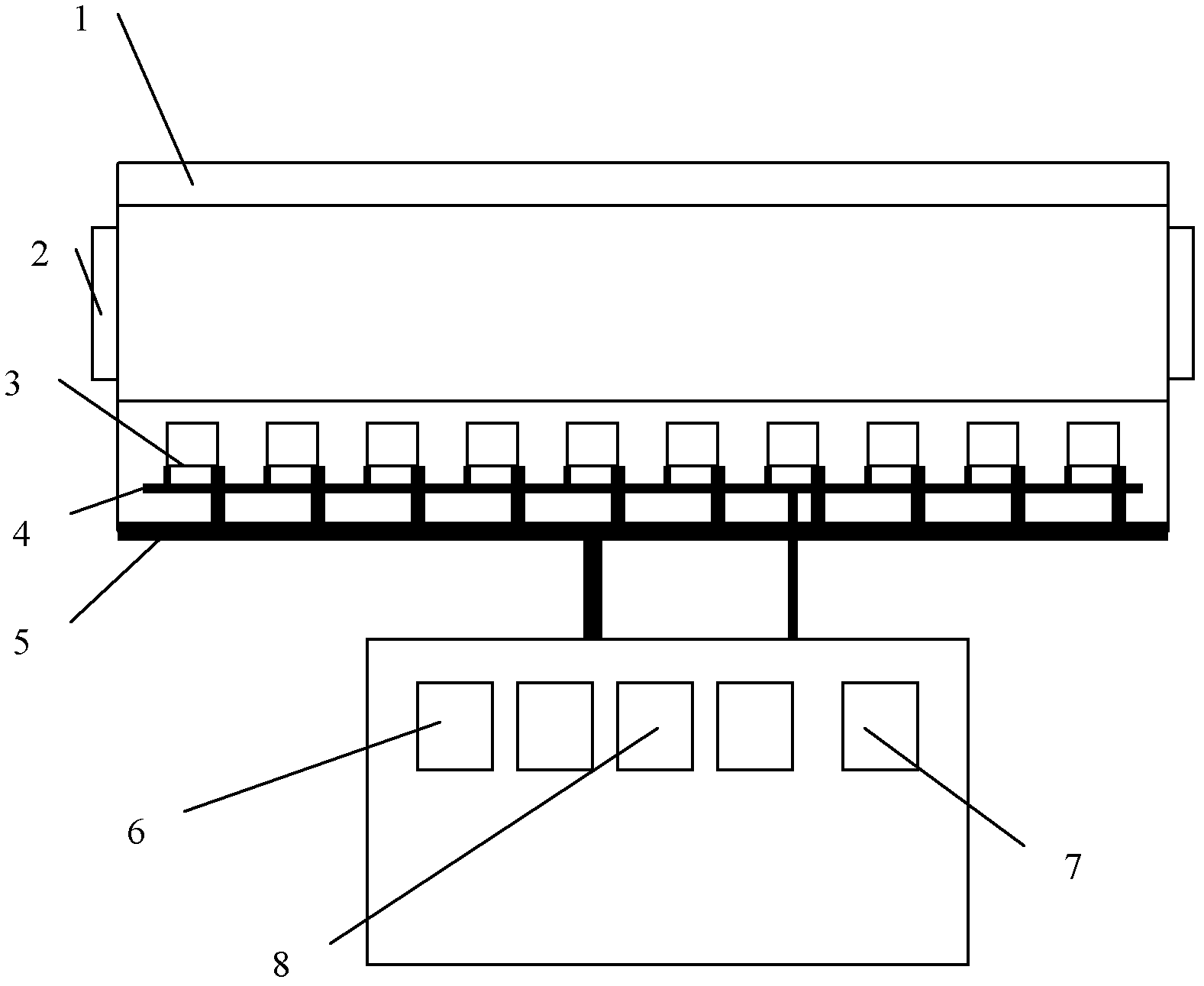
[0014] Such as figure 1 As shown, the low-carbon energy-saving gas heat treatment tunnel furnace of the present invention mainly includes: tunnel furnace body 1, furnace door 2, burner 3, gas pipeline 4, air supply pipeline 5, oxygen-enriched generator 6, gas supply device 7 and Fan 8, etc., a plurality of burners 3 are arranged under the tunnel furnace body 1, the burners 3 are connected to the gas supply device 7 through the gas pipeline 4, and the burners 3 are connected to the oxygen-enriched generator 6 and the fan 8 through the air supply pipeline 5, Furnace doors 2 are arranged on both sides of the tunnel furnace body 1 . In this embodiment, 10 burners are evenly distributed, and the interval between adjacent burners is 1.5 meters.

[0015] In the present invention, the burner may be a swirl burner (patent number 200920351711.8) or a cyclone gas burner (patent number 200920013848.2).

[0016] Principle of operation of the present invention:

[0017] First ignite the ...


PUM


Abstract

The invention relates to the field of heat treatment, particularly to a low carbon and energy-saving gas heat treatment tunnel kiln, and aims to solve problems of low fuel combustion rate, low combustion temperature and the like existing in the gas heat treatment tunnel kilns in the prior art. The gas heat treatment tunnel kiln is provided with a burner and a rich oxygen generator, wherein the burner is connected with a gas transmitting device through a gas pipeline, the burner is connected with the rich oxygen generator and a draught fan through an air supply pipeline, and the burner is of a vortex type or a whirlwind type. Due to the adoption of the vortex type burner or the whirlwind type burner, emission capacity of carbon monoxide is 20 times less than the emission capacity of carbon monoxide of ordinary burners, and gases can be burned sufficiently. Emission standard of ordinary burners is less than 0.20 % and the emission standard of the vortex type burners is less than 0.011%. Due to the fact that the rich oxygen generator is additionally arranged on an air supply system, gas supply quality can be saved about 10%.

Description

technical field [0001] The invention relates to the field of heat treatment, in particular to a low-carbon energy-saving gas heat treatment tunnel furnace. Background technique [0002] The use of burners in gas-fired heat treatment tunnel furnaces is an indispensable equipment. Especially in recent years, with the development of science and technology and the requirements of environmental protection, people's demand for burners that use gas, liquid, and gas-liquid mixtures as fuel is increasing. more and more widely. However, with the energy crisis and the increase in fuel prices, the society must be required to provide more efficient, energy-saving and environmentally friendly burners. [0003] At present, the burners of traditional gas-fired heat treatment tunnel furnaces often have unburned molecules discharged with the tail gas, resulting in incomplete combustion, low fuel combustion rate, and low combustion temperature, resulting in the escape of combustion molecules....

Claims


Application Information

Patent Timeline
Patent Type & Authority Applications(China)
IPC IPC(8): F27B9/36F23L7/00
CPCY02E20/34
Inventor 龙康王胜刚
Owner INST OF METAL RESEARCH - CHINESE ACAD OF SCI
Learn More