Fatigue testing machine used for small module wheel gear symmetry fatigue test

A technology of fatigue testing machine and small modulus gear, which is applied in the direction of machine gear/transmission mechanism testing, etc., can solve the problems of wasting experimental information, high experimental cost, and low experimental efficiency, and achieve the effect of reducing experimental cost and improving experimental efficiency

Inactive Publication Date: 2013-06-05
HARBIN INST OF TECH
View PDF5 Cites 15 Cited by
  • Summary
  • Abstract
  • Description
  • Claims
  • Application Information

AI Technical Summary

Problems solved by technology

[0004] The present invention solves the problems that the existing fatigue testing machine using the A test method to test the fatigue characteristics of small modulus gears can only obtain one experimental

Method used


Image

  • Fatigue testing machine used for small module wheel gear symmetry fatigue test
  • Fatigue testing machine used for small module wheel gear symmetry fatigue test
  • Fatigue testing machine used for small module wheel gear symmetry fatigue test

Examples


specific Embodiment approach 1

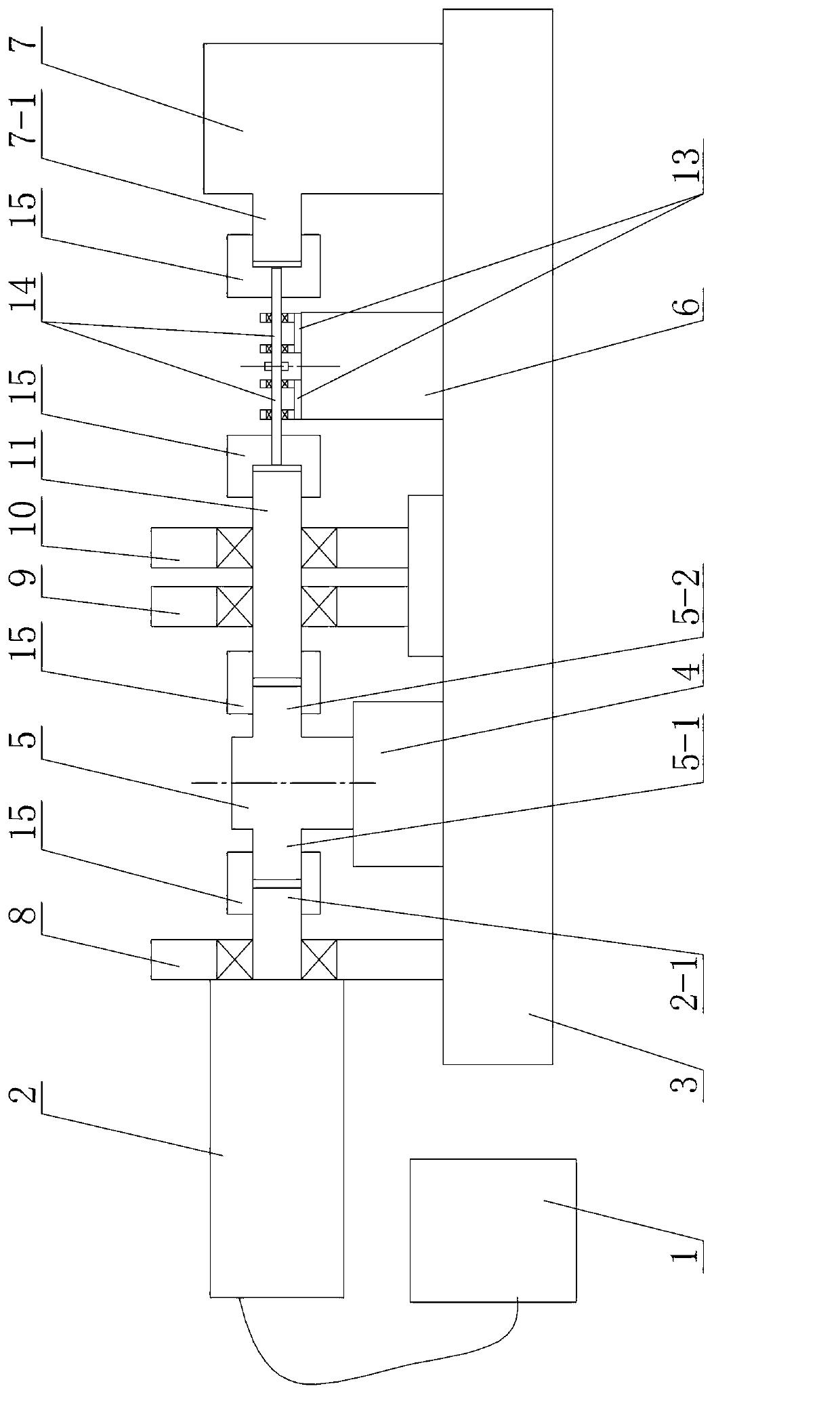
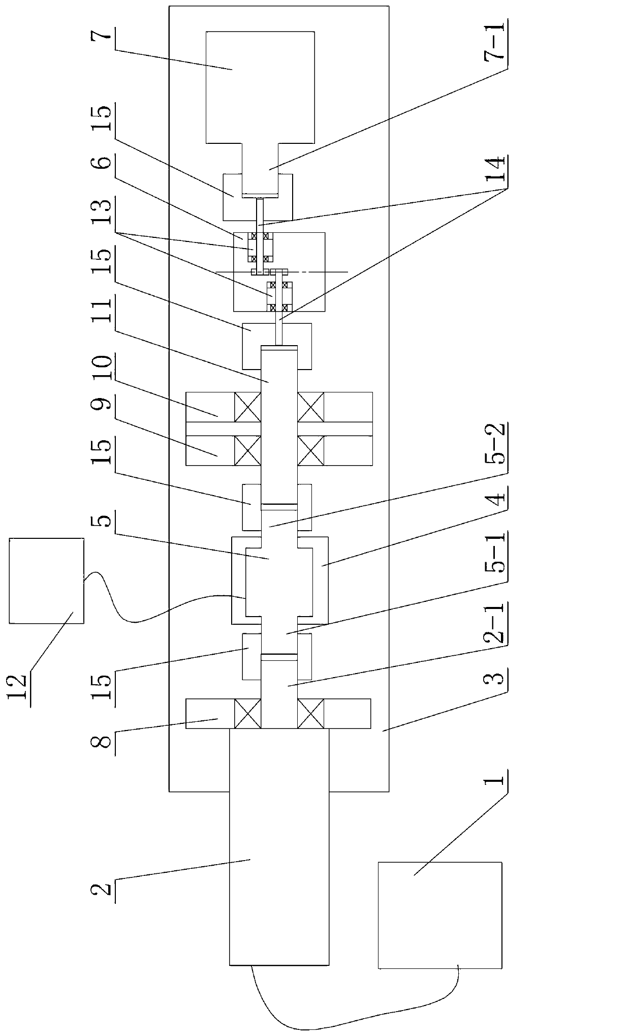
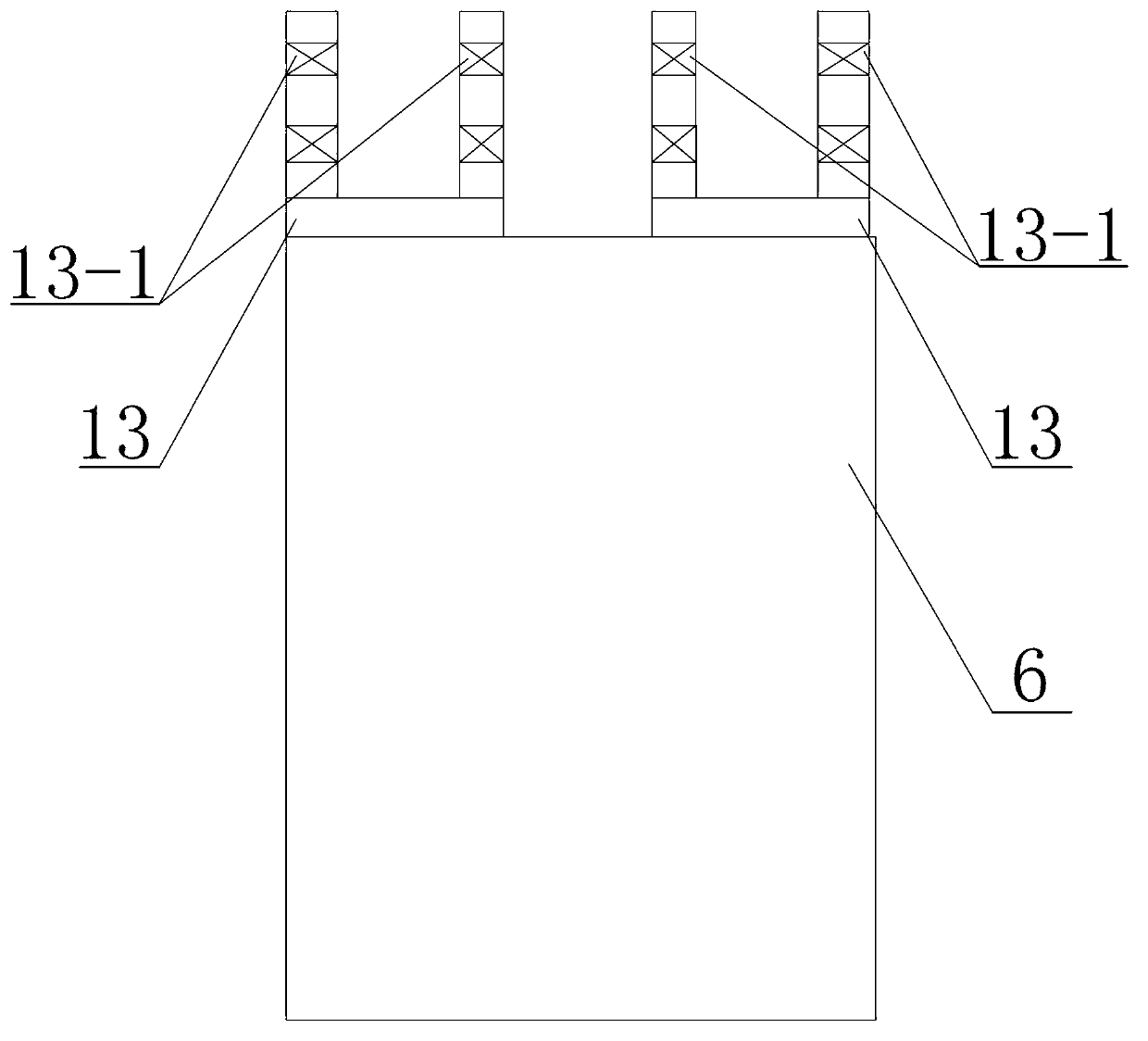
[0009] Specific implementation mode one: combine Figure 1 to Figure 7 To illustrate, a fatigue testing machine for symmetrical fatigue testing of small modulus gears in this embodiment includes a controller 1, a servo motor 2, a supporting base 3, a supporting base 4, a torque sensor 5, a micro-motion platform 6, and a magnetic powder brake 7 , the first bearing support 8, the second bearing support 9, the third bearing support 10, the connecting shaft 11, the computer 12, two mounting supports 13, two gear assembly shafts 14 and a plurality of couplings 15, The upper surface of the support base plate 3 is sequentially fixed with the first bearing support 8, the support base 4, the second bearing support 9, the third bearing support 10, the micro-motion platform 6 and the magnetic powder brake 7 along the length direction of the support base plate 3. , a torque sensor 5 is installed on the support base 4, and a mounting support 13 is respectively installed on the two ends of ...

specific Embodiment approach 2

[0010] Specific implementation mode two: combination figure 1 and figure 2 Note that the plurality of couplings 15 in this embodiment are all rigid couplings. Other components and connections are the same as those in the first embodiment.

[0011] Working principle: Firstly, the components of the fatigue testing machine are installed, the controller 1 controls the rotation of the servo motor 2, and the servo motor 2 transmits the torque to the torque sensor 5 and the connecting shaft 11 in turn, and finally transmits the torque to the two meshing shafts Adjust the micro-movement platform 6 to make each component run smoothly, then start the magnetic powder brake 7 to apply a constant torque to the two small modulus gears 16, and the torque sensor 5 synchronously collects the meshing transmission of the two small modulus gears 16 The experimental data in the process is finally input into the computer 12 to analyze the fatigue characteristics of the two small modulus gears 16...


PUM


Abstract

Disclosed is a fatigue testing machine used for a small module wheel gear symmetry fatigue test. The invention relates to a wheel gear fatigue testing machine. The problems that only one experimental data can be obtained by the existing testing machine by taking an A test method to test the small module wheel gear fatigue feature, vast experiment information is wasted, the experiment efficiency is low and the experiment cost is high are solved. A main shaft of a servo motor, an input shaft of moment of force sensor, an output shaft of the moment of force sensor and a connecting shaft are arranged with a wheel gear assembling shaft close to one side of the connecting shaft in a coaxial mode. One end of the connecting shaft is connected with the output shaft of the moment of force sensor in a coaxial mode through a coupler. The other end of the connecting shaft is connected with the wheel gear assembling shaft close to one side of the connecting shaft in a coaxial mode through the coupler. Two to-be tested small module wheel gears are respectively installed on two wheel gear assembling shafts and the two small module wheel gears are arranged in a mutual meshing mode. The fatigue testing machine used for the small module wheel gear symmetry fatigue test is used for testing the fatigue feature of the small module wheel gear.

Description

technical field [0001] The invention relates to a gear fatigue testing machine. Background technique [0002] According to the standard GBT14230-1993, there are two types of gear bending fatigue strength test methods, which are referred to as A test method (gear bench running test) and B test method (gear tooth pulsation loading test). At present, many gear tests adopt the B test method, which is generally based on the material fatigue testing machine, and the gear is loaded through a special conversion fixture. Generally, B test method can only achieve pulsating loading, and its load action point is the highest point of single tooth meshing. The data obtained by B test method needs to be assisted by conversion coefficient when used in mechanical design, which is compatible with the conventional gear part design method. It is obvious that the running state of the gear in the A test method is more in line with the actual situation, and the test data is more intuitive and mor...

Claims


Application Information

Patent Timeline
IPC IPC(8): G01M13/02
Inventor 李跃峰潘旭东林卓王广林
Owner HARBIN INST OF TECH
Why Eureka
Try Eureka