mass balance unit

A technology of mass balancing and balancing shaft, applied in engine components, mechanical equipment, rotating parts that resist centrifugal force, etc., can solve the problems of large weight, high cost, unbalanced balancing shaft, etc., and achieve the effect of unaffected stability.

Inactive Publication Date: 2015-09-16
MAGNA POWERTRAIN AG & CO KG
View PDF4 Cites 0 Cited by
  • Summary
  • Abstract
  • Description
  • Claims
  • Application Information

AI Technical Summary

Problems solved by technology

[0004] However, due to the imbalance caused by the balance shaft, the balance shaft and its bearings are also heavily loaded, so a stable design of the balance shaft and a dimensional design of the bearings are required
But this leads to a large weight and an undesired high cost of the mass balance unit

Method used


Image

  • mass balance unit
  • mass balance unit
  • mass balance unit

Examples


Embodiment Construction

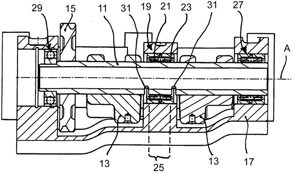
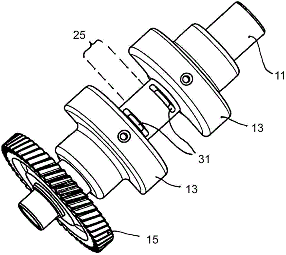
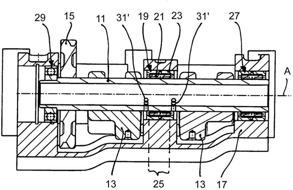
[0031] exist Figure 1a and Figure 1b The mass balance unit shown in includes a hollow, ie tubular, balance shaft 11 . Two balance weights 13 are fixed on the balance shaft 11 by, for example, thermocompression connection, screw connection, welding or positioning pins. In order to create an unbalance, the balance weights 13 are substantially in the form of semi-cylindrical parts with two fixing clips molded on them, wherein, with respect to the axis of rotation A of the balance shaft 11, the angular orientation of one balance weight 13 corresponds to The angular orientation of the other counterweight 13 corresponds. In addition, a drive wheel 15 is also fixed to the balance shaft 11 by, for example, thermocompression bonding. The drive wheel 15 can be directly drivingly connected to the crankshaft of the associated internal combustion engine to form a transmission stage. Alternatively, the drive wheel 15 can be drivingly connected to a corresponding drive wheel of a balanc...


PUM


Abstract

A mass balancing unit having a hollow balancing shaft, at least one balancing weight which is provided on the balancing shaft and at least one roller bearing which has an outer bearing ring and a plurality of roller members. A longitudinal portion of the balancing shaft forms an inner bearing ring, the roller members being received between the outer bearing ring and the longitudinal portion of the balancing shaft. Adjacent to the longitudinal portion, the balancing shaft has at least one recess in order to reduce the rigidity of the longitudinal portion of the balancing shaft in a radial direction.

Description

technical field [0001] The invention relates to a mass compensation unit with a hollow balancing shaft, at least one balancing weight provided on the balancing shaft, and at least one rolling bearing having a bearing outer ring and a plurality of rolling bodies, In this case, the longitudinal section of the balancing shaft forms the bearing inner ring, and the rolling bodies are accommodated between the bearing outer ring and the longitudinal section of the balancing shaft. Background technique [0002] The purpose of a mass balance unit with one or more balance shafts is to balance the inertial forces and / or moments of inertia that typically occur in internal combustion engines. For this purpose, at least one balancing weight is provided, in particular mounted in a rotationally fixed manner, on each balancing shaft in order to create an unbalance. The balance shaft is drivingly connected to the crankshaft of the internal combustion engine, whereby the balance shaft and the...

Claims


Application Information

Patent Timeline
Patent Type & Authority Patents(China)
IPC IPC(8): F16F15/26
CPCY10T74/2128F16C3/20Y10T464/50F16F15/268F16F15/264F16C3/02F16C19/466F16C2361/53F16F15/26
Inventor M.肖伯
Owner MAGNA POWERTRAIN AG & CO KG
Why Eureka
Try Eureka