
Pipe groove type liquid distributor applied to flue gas desulfurization tower

A liquid distributor and liquid distribution pipe technology, applied in the field of column internals, can solve problems such as easy blockage of small holes and difficulty in uniform flow output, and achieve the effects of reducing liquid flow rate, improving liquid distribution uniformity, and ensuring separation efficiency.

Active Publication Date: 2013-06-12
TIANJIN TIANDA TIANJIU TECH CO LTD
View PDF5 Cites 7 Cited by
  • Summary
  • Abstract
  • Description
  • Claims
  • Application Information

AI Technical Summary

Problems solved by technology

The tubular liquid distributor is composed of row-pipe or ring-pipe open-hole pipes. Since the liquid flows at a variable speed in the equal-diameter tubular liquid distributor, that is, the flow rate of the liquid along its process gradually decreases, and the static pressure changes accordingly. , so the tube-type liquid distributor has the defects that it is difficult to equalize the output of each orifice, and the small holes are easy to be blocked.

Method used


Image

  • Pipe groove type liquid distributor applied to flue gas desulfurization tower
  • Pipe groove type liquid distributor applied to flue gas desulfurization tower
  • Pipe groove type liquid distributor applied to flue gas desulfurization tower

Examples


Embodiment Construction

[0020] Further illustrate the present invention below in conjunction with embodiment and accompanying drawing.

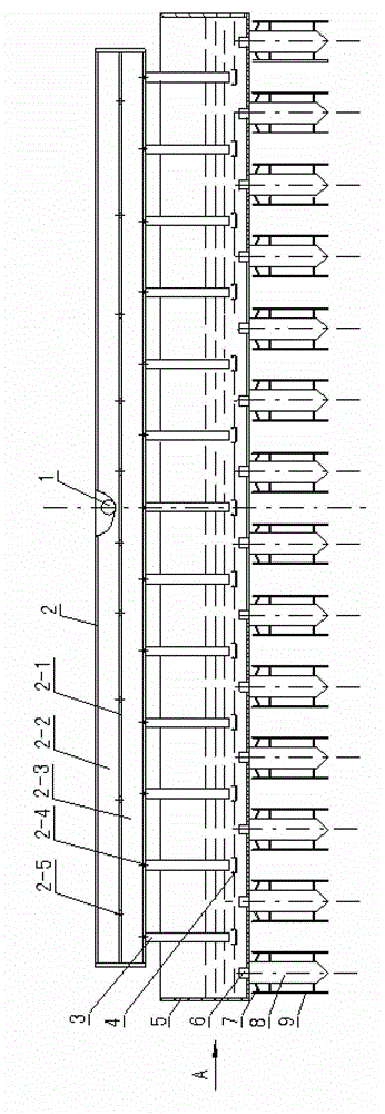
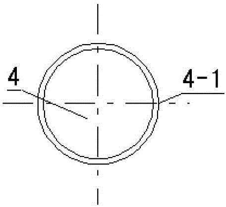
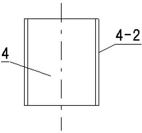
[0021] Such as figure 1 , 2 , The embodiment shown in 3 and 4, the liquid distributor is composed of a liquid inlet pipe 1, a liquid distribution pipe 2, a primary tank 5, and a secondary tank 8 connected in sequence.

[0022] The liquid distribution pipe 2 is divided into a first-stage liquid distribution pipe 2-2 and a second-stage liquid distribution pipe 2-3 connected up and down by an intermediate partition 2-1 that is axial to the liquid distribution pipe, and the liquid inlet pipe 1 is connected to At the axial bisection of the first-stage liquid distribution pipe 2-2.

[0023] The middle partition 2-1 is symmetrically arranged on both sides corresponding to the axis of the liquid inlet pipe, and the hole interval is gradually thinned. The liquid distribution holes 2-4 are arranged at equal intervals and equal diameters, and the apertures of the liquid dis...


PUM

PropertyMeasurementUnit
Diameteraaaaaaaaaa

Abstract

The invention relates to a pipe groove type liquid distributor applied to a flue gas desulfurization tower. The pipe groove type liquid distributor is composed of a liquid inlet tube, a liquid distributing pipe, a first-stage groove and a second-stage groove which are engaged with each other, wherein the liquid distributing pipe is divided into two stages which are engaged up and down through a middle partition board with variable interval equant liquid distributing holes; a second-stage bottom surface is provided with equal interval equant liquid distributing holes and liquid sealing pipes; the outlet end of each liquid sealing pipe is provided with a buffer; the bottom of the first-stage groove is provided with the second-stage groove vertical to the first-stage groove in a long axis direction at the middle position between corresponding adjacent liquid sealing pipes; uniform section rectangular liquid distribution liquid sealing pipes respectively inserted in each second-stage groove are arranged at the bottom of the first-stage groove; upper and lower liquid discharge holes at equal intervals are formed in both side groove boards of the second-stage groove; an anti-blocking baffle board is arranged inside each upper liquid discharge hole, and a flow guide groove board correspondingly engaged with a wire distributing board is arranged outside each upper liquid discharge hole; and a liquid distributing board is arranged at the lower part of each lower liquid discharge hole of the second-stage groove. The pipe groove type liquid distributor has the characteristics of liquid distribution uniformity, impact foam generation prevention, entrainment prevention and blockage prevention, and can be widely applied to large, middle and small containers for absorption and distillation such as flue gas desulfurization.

Description

technical field [0001] The invention belongs to tower internals of chemical packing towers, in particular to a tube and groove liquid distributor applied to flue gas desulfurization towers. Background technique [0002] In order to reduce the amplification effect caused by poor liquid distribution and give full play to the efficiency of the packing, a liquid distributor must be installed in the packed tower to make the liquid evenly distributed on the top of the packing layer. [0003] The performance of the liquid distributor not only affects the uniformity of its liquid distribution and the mass transfer efficiency of the packing, but also affects the operating elasticity of the packed tower. Therefore, the liquid distributor is one of the most critical internals in the packed column. [0004] There are many types of liquid distributors, and pipe liquid distributors and trough liquid distributors are two general-purpose distributors. The tubular liquid distributor is com...

Claims


Application Information

Patent Timeline
IPC IPC(8): B01D53/18
Inventor 赵汝文王斌王平于健田桂林
Owner TIANJIN TIANDA TIANJIU TECH CO LTD
Learn More