Transmission device

A transmission device and transmission shaft technology, which is applied to wheel transmission devices, rotary transmission devices, transmission parts, etc., can solve the problems of reduced meshing accuracy, trembling, and reduced service life of gear pairs, so as to reduce gear meshing noise and avoid Shivering and numbness, the effect of eliminating abnormal wear

Inactive Publication Date: 2013-06-12
重庆弘劼机械有限公司
View PDF5 Cites 3 Cited by
  • Summary
  • Abstract
  • Description
  • Claims
  • Application Information

AI Technical Summary

Problems solved by technology

[0003] The existing bevel gear transmission structure includes an input end bevel gear pair connected with the pedal, an output end bevel gear pair connected with the rear wheel hub, and a transmission shaft connecting the input end bevel gear pair and the output end bevel gear pair. There is a rigid connection between the bevel gear at the input end and the central shaft, and the structure is simple, but the gap between the gear pairs is not easy to control, which will easily cause the noise of the gear pair, reduce the meshing accuracy of the gear pair, and cause abnormal wear of the gears, reducing the service life.
In addition, the current bevel gear pairs are lubricated with grease. The grease adheres to the gear surface, and the wear debris between the gear pairs also adheres to the gear surface. During the operation of the gear pair, the wear debris continuously hones the gear, resulting in Abnormal wear of gear pairs, early failure and hidden dangers of broken teeth
It will also cause functional loss, loud noise, trembling, numbness, etc., which will bring personal injury or property loss to riders, and hidden dangers of poor suitability

Method used


Image

  • Transmission device
  • Transmission device
  • Transmission device

Examples


Embodiment Construction

[0031] The present invention will be described in further detail below in conjunction with specific embodiments and accompanying drawings.

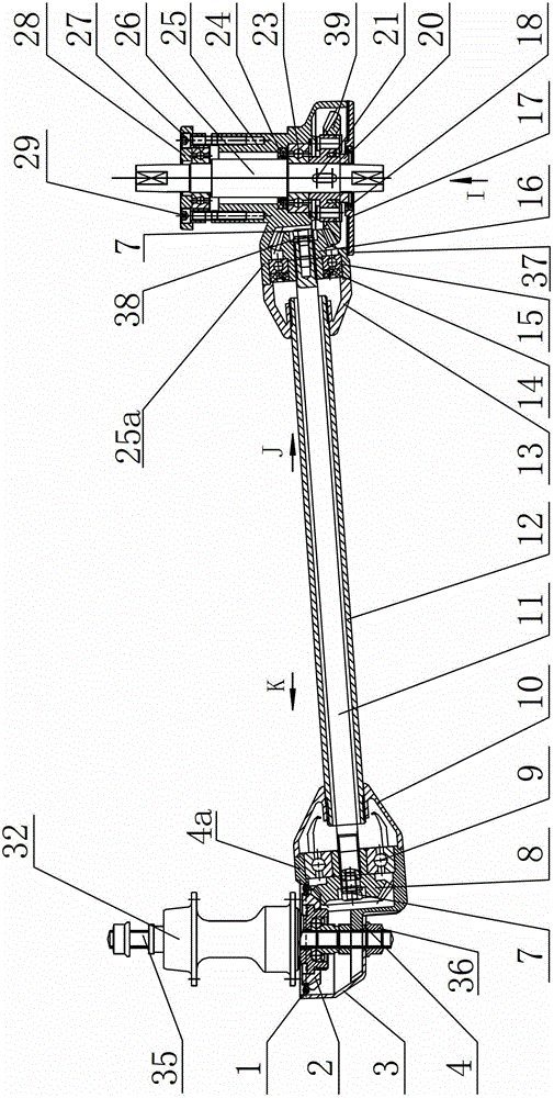
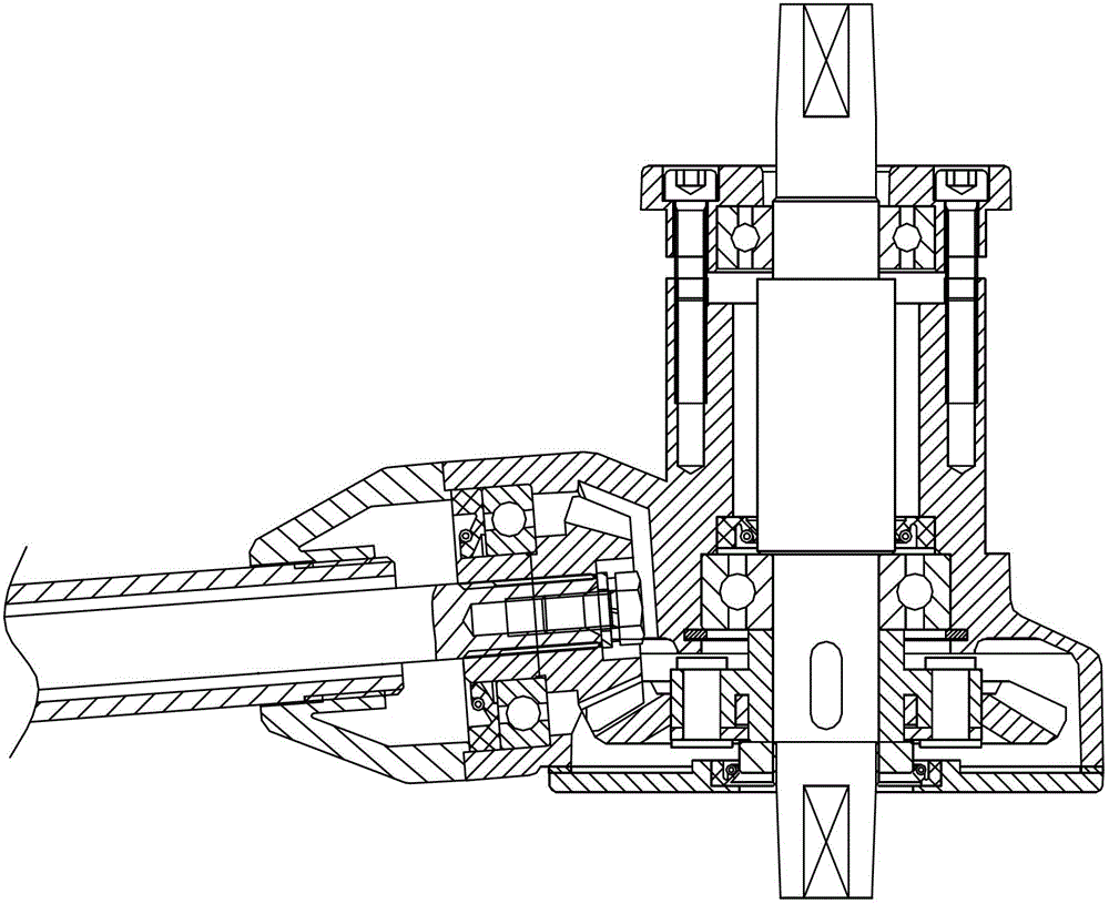
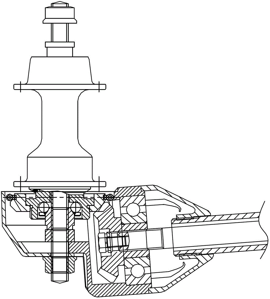
[0032] a kind of like Figure 1-4The transmission device shown is specifically an oil-bath shaft transmission device with a buffer function for replacing a traditional bicycle chain transmission system, which includes an input gearbox 25 provided with a bicycle pedal center shaft 26, and a hub 32 provided with a rear wheel hub of a bicycle. Output gear box 4, the first driving bevel gear 39 and the first driven bevel gear 16 which mesh with each other are arranged in the input gear box 25, and the first driven bevel gear 16 and the wheel in the output gear box 4 The two systems are connected by power transmission through the transmission shaft 11, and the first driving bevel gear 39 and the central shaft 26 are fixedly connected by a bushing 41, and the bushing 41 is fixed on the central shaft 26 through a spline limit, The first driving...


PUM


Abstract

The invention discloses an oil bath type transmission device with a buffer function, which comprises an output gear box and an input gear box, wherein the input gear box is provided with a first driving bevel gear and a first driven bevel gear that are engaged with each other; the first driven bevel gear is in power transferring connection with a wheel train in the output gear box by a transmission shaft; the first driving bevel gear is fixedly connected with a middle shaft of a bicycle by a shaft sleeve; the shaft sleeve is limited and fixed on the middle shaft by a spline; the first driving bevel gear is arranged on a plummer block of the shaft sleeve in a sleeving manner, positioned and fixed; a groove and convex teeth that are matched mutually are formed between the adjacent end faces of a shaft shoulder of the shaft sleeve and the first driving bevel gear; a buffer sleeve is arranged among the groove and the convex teeth; a counter bore is formed in the end face of the first driving bevel gear adjacent to the shaft shoulder of the shaft sleeve; and a shock-absorbing pad which is higher than the counter bore and pushes against the shaft sleeve and the first driving bevel gear respectively is arranged in the counter bore. According to the transmission device, a gap between a gear pair is eliminated, and noise, trembling and numbness of the gear pair is reduced.

Description

technical field [0001] The invention belongs to the transmission system of an automatic vehicle, and in particular relates to an oil-bath shaft transmission device with a buffer function for replacing a traditional bicycle chain transmission system. Background technique [0002] The transmission system of traditional bicycles usually adopts the transmission structure of sprockets and chains. Although this transmission structure is equipped with chain baffles, it is still an open transmission structure. The rider's trousers or skirt are easily broken by the chain or sprocket. It may even cause the rider to fall and cause property damage or personal injury. At the same time, the chain is easy to break or fall off after being used for a period of time, and needs to be reconnected or installed, which brings a lot of troubles to the rider. For this reason, those skilled in the art have improved, and adopted the conical gear transmission structure to replace the sprocket chain tr...

Claims


Application Information

Patent Timeline
Patent Type & Authority Applications(China)
IPC IPC(8): B62M17/00B62M11/00F16H57/028F16H57/029F16H57/02F16H57/04
Inventor 赵蓟瑜
Owner 重庆弘劼机械有限公司
Why Eureka
Try Eureka