Pneumatic layout of vertical taking-off and landing aircraft with tilted duct

A vertical take-off and landing, aerodynamic layout technology, applied in the field of modern aerospace, can solve the problems of aircraft payload limitation, affecting aircraft fuel capacity, reducing aircraft range, etc., to achieve compact structure, increase pressure difference between upper and lower wing surfaces, and control flexible effects

Inactive Publication Date: 2013-06-12
NORTHWESTERN POLYTECHNICAL UNIV
View PDF6 Cites 40 Cited by
  • Summary
  • Abstract
  • Description
  • Claims
  • Application Information

AI Technical Summary

Problems solved by technology

However, due to the vertical take-off and landing of the tilt-rotor aircraft, the take-off weight of the aircraft can only be about 85% of the thrust of the engine, which greatly limits the payload of th

Method used


Image

  • Pneumatic layout of vertical taking-off and landing aircraft with tilted duct
  • Pneumatic layout of vertical taking-off and landing aircraft with tilted duct
  • Pneumatic layout of vertical taking-off and landing aircraft with tilted duct

Examples


Embodiment Construction

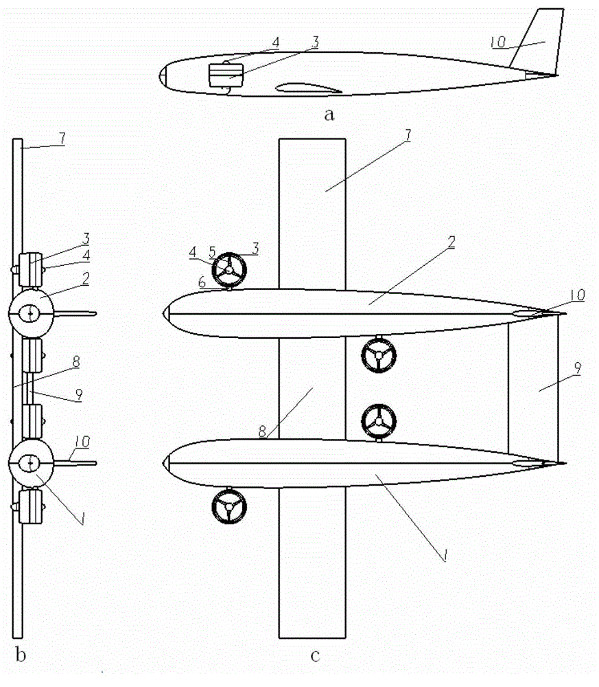
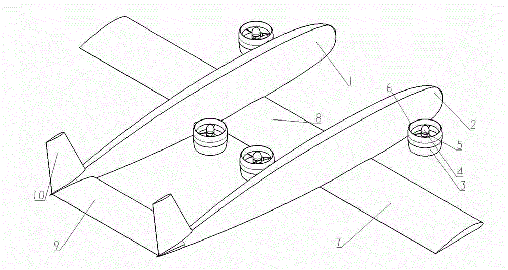
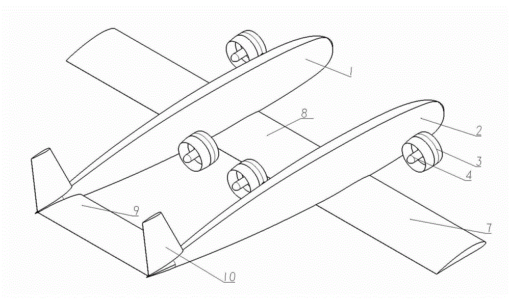
[0031] Such as figure 1 , figure 2 , image 3 Shown are the appearance diagram of the aircraft in the vertical takeoff and landing state, the appearance diagram of the aircraft in the cruising state, and the three views of the aircraft in the vertical takeoff and landing state.

[0032] The present embodiment is an aerodynamic layout of a tilting duct VTOL aircraft, comprising a left fuselage 1, a right fuselage 2, a wing 7, a central wing 8, a horizontal tail 9, a vertical tail 10 and 4 ducted fans .

[0033] Such as Figure 1~3 As shown, the present embodiment adopts double fuselages, double vertical empennages, and the wing is a horizontal lower single wing, and the center of gravity of the whole machine is positioned at the 25% relative chord length position of the wing. The 4 ducted fans are divided into two groups, one of which is the front ducted fan and the other is the rear ducted fan. The front ducted fans are symmetrically installed on the outside of each fuse...


PUM


Abstract

The invention discloses a pneumatic layout of a vertical taking-off and landing aircraft with a tilted duct. The pneumatic layout is characterized in that front duct fans are symmetrically arranged at the outer sides of the head parts of all the aircraft bodies; rear duct fans are symmetrically arranged at the inner sides of the middle parts of all the aircraft bodies; and all the duct fans are respectively connected with transmission components in the aircraft bodies by duct rotating shafts in the transmission components. The axial distance between protection points of the axial lines of all the duct rotating shafts on the axial lines of the aircraft bodies and the center of gravity of the whole aircraft along the aircraft bodies is 1.125 times of the chord length of wings. In the pneumatic layout, the duct fans can rotate around the duct rotating shafts; when the aircraft takes off or lands vertically, the duct fans are positioned at the vertical 90-degree position, the thrust vector is upward; in the transition stage, the duct fans rotate forwards around the duct rotating shafts; and in the cruise stage, the duct fans are positioned at a horizontal 0-degree position, and the thrust vector is forward, so that vertical taking off and landing and high-speed cruise flying are realized. The pneumatic layout disclosed by the invention has the advantages of high pneumatic efficiency, compact structure, strong reliability, strong maneuverability, flexible operation, long voyage and low noise and the like.

Description

technical field [0001] The invention relates to the field of modern aerospace, in particular to an aerodynamic layout of a vertical take-off and landing vehicle with a tilting duct. Background technique [0002] During the take-off and landing phase, the aircraft should reduce the ground speed and ground speed as much as possible, reduce or even get rid of the dependence on the airport conditions, so that the aircraft can take off and land safely in various environments, and improve the flexibility and convenience of the aircraft. in order to better complete the flight mission. At present, the short-distance / vertical take-off and landing aircraft has attracted more and more attention from the military and civilians. It has the characteristics of low site conditions, strong maneuverability, and good concealment. , urban transportation and other civil fields have great application potential. [0003] At present, STOL technologies mainly include: 1. Using advanced aerodynamic...

Claims


Application Information

Patent Timeline
IPC IPC(8): B64C29/00
Inventor 叶正寅杨磊张伟伟
Owner NORTHWESTERN POLYTECHNICAL UNIV
Why Eureka
Try Eureka