Strip steel processing device and strip steel annealing and recoiling technology

A processing device and technology for strip steel, applied in the direction of coiling strip, transportation and packaging, thin material processing, etc., can solve the problems of increased processing cost, waste of resources, difficult operation, etc., to reduce processing cost, save electricity, and easily effect of operation

Inactive Publication Date: 2013-06-12
唐山宏阔科技有限公司
View PDF6 Cites 2 Cited by
  • Summary
  • Abstract
  • Description
  • Claims
  • Application Information

AI Technical Summary

Problems solved by technology

If the rolled finished strip needs to be annealed, the internal stress must be relieved, otherwise the strip layers will stick together after annealing, resulting in loss
The existing technology to reduce the internal stress is to use a feeding device to unroll the strip steel layer by layer from the outer layer, pass through the compacting device, and use a receiving device to wind up the strip layer by layer, which is time-consuming and consumes electric energy.
In the prior art, in order to prevent scratches on the surface of the steel strip, two felts are placed on the pressing device, and the steel strip passes through the middle of the felts. The felts are often worn out, and the felts need to be replaced frequently, resulting in waste of resources and increased processing costs.
The existing technology is not easy to operate, because the steel strip is unrolled layer by layer from the outer layer and then wound up layer by layer with the receiving device, which makes the moving distance of the steel strip too long. If the pressure of the pressing device is too large, the steel strip layer is easy to stick after annealing. If the pressure is too small, the steel strip will swing horizontally during winding, resulting in irregular winding
Because the coiled steel strips are laid flat and superimposed during annealing, the edges of the untidy coiled steel strips will be pressed into wrinkles, which will affect the product quality

Method used


Image

  • Strip steel processing device and strip steel annealing and recoiling technology
  • Strip steel processing device and strip steel annealing and recoiling technology

Examples


Embodiment Construction

[0024] In order to make the technical problems, technical solutions and beneficial effects solved by the present invention clearer, the present invention will be further described in detail below in conjunction with the accompanying drawings and embodiments. It should be understood that the specific embodiments described here are only used to explain the present invention, not to limit the present invention.

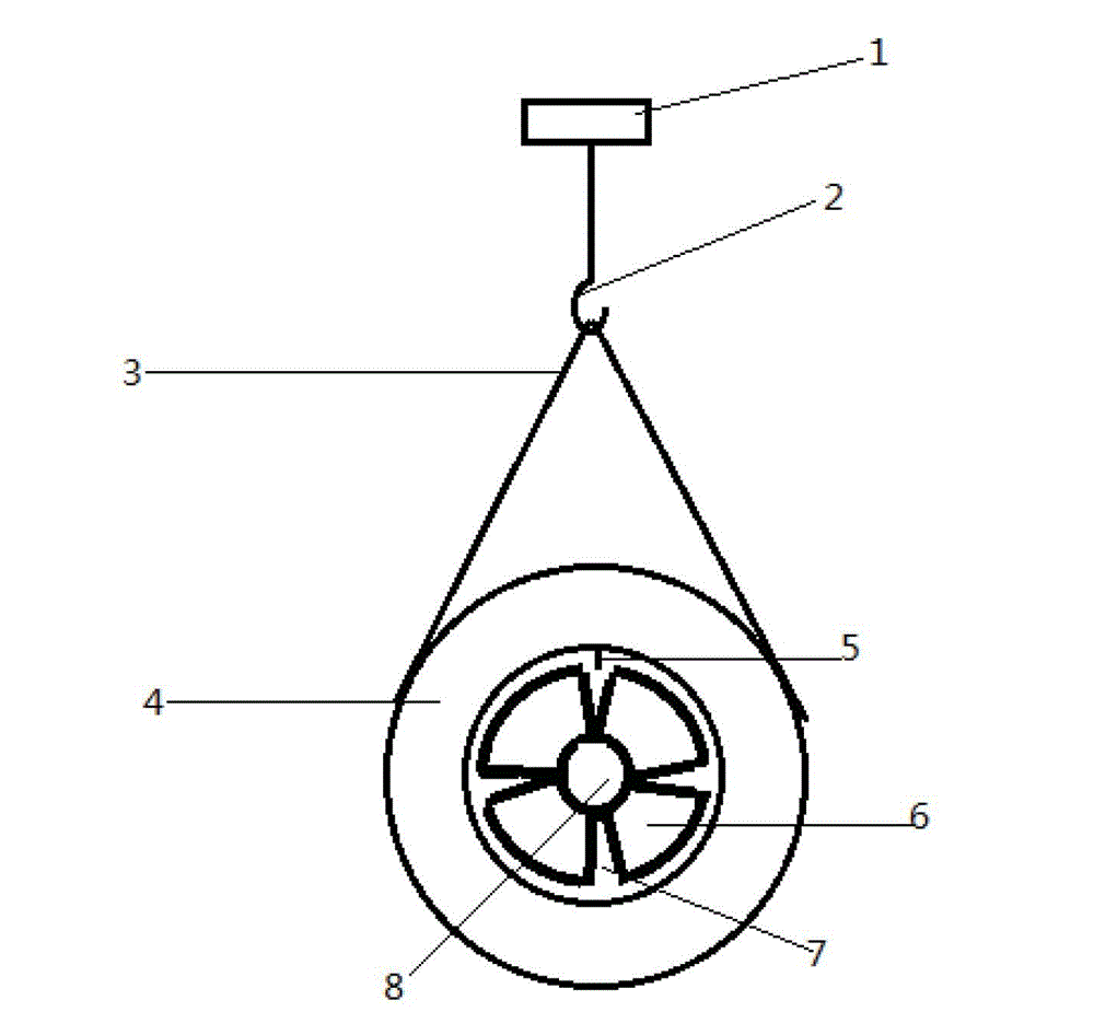
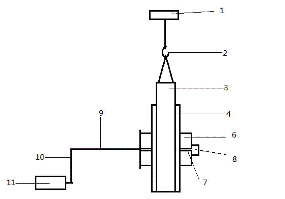
[0025] Such as Figure 1 to Figure 2 A kind of strip steel 4 processing device shown, comprises crane 1, suspender 3, strip steel receiving shaft and power unit 11, and described suspender 3 is suspended on the described crane 1, and described strip steel receiving shaft and The power unit 11 is transmission-connected; the strip steel receiving shaft includes a coil expansion and contraction nut 8 and a material receiving coil 6 arranged in a petal shape, and a coil expansion and contraction gap 7 is arranged between adjacent said receiving coils 6 , the crimp expansion...


PUM

PropertyMeasurementUnit
diameteraaaaaaaaaa

Abstract

The invention discloses a strip steel processing device and a strip steel annealing and recoiling technology. The device comprises an overhead travelling crane, a hanging strip, a strip steel material collecting shaft and a power device, wherein the hanging strip is hung on the overhead travelling crane; the strip steel material collecting shaft is in transmission connection with the power device, and comprises a curled expansion nut and petal-shaped curled material collecting pieces; curled expansion intervals are formed between the adjacent curled material collecting pieces; and the curled expansion nut adjusts the size of diameters of the curled material collecting pieces and the size of the curled expansion intervals. According to the strip steel processing device and the strip steel annealing and recoiling technology, an emptying device and a clamping device are omitted; the efficiency is improved greatly; the electric energy is saved; the processing cost is lowered greatly; orderliness of rolled finished strip steel cannot be changed; the tightness for coiling the strip steel can be adjusted automatically by utilizing an inertial acting force; and the operation is simple.

Description

technical field [0001] The invention relates to the technical field of sheet metal processing equipment, in particular to a strip steel processing device and a strip steel annealing and recoiling process. Background technique [0002] Cold-rolled strip steel is processed in coils. When the rolling mill is cold-rolling strip steel, it needs a certain tension to straighten the raw material strip steel and the finished strip steel to work normally. Therefore, there is a certain stress inside the rolled finished strip, that is, the inner strip layers of the rolled finished strip are very tightly attached together. If the rolled finished strip still needs to be annealed, the internal stress must be relieved, otherwise the strip layers will stick together after annealing, resulting in loss. The existing technology to reduce the internal stress is to use a feeding device to unroll the strip steel layer by layer from the outer layer, pass through a compacting device, and use a rec...

Claims


Application Information

Patent Timeline
Patent Type & Authority Applications(China)
IPC IPC(8): B65H18/10
Inventor 王良
Owner 唐山宏阔科技有限公司
Why Eureka
Try Eureka