Supercharge Your Innovation With Domain-Expert AI Agents!

Section steel soil cement mixing pile with longitudinal displacement mechanism

A cement-soil mixing pile and section steel technology, which is applied in sheet pile walls, foundation structure engineering, construction, etc., can solve problems such as complicated operation, time-consuming and laborious operation, low production efficiency, and inconvenient positioning of construction units

Inactive Publication Date: 2013-06-12
WUHAN TIANBAO ENG MACHINERY
View PDF10 Cites 8 Cited by
  • Summary
  • Abstract
  • Description
  • Claims
  • Application Information

AI Technical Summary

Problems solved by technology

[0003] The cement-soil mixing pile machine produced by the existing technology usually adopts the crawler walking system for the walking alignment device, such as the Chinese invention patent "Construction Machinery for Cement-soil Core Inserted Composite Pile" (application number: 200410093838.6), the device is expensive, and the construction unit positioning It is very inconvenient, and the crawler walking system must be repeatedly operated, the operation is complicated, time-consuming and laborious, and the production efficiency is low; The bottom is equipped with a hydraulic walking system, which mainly includes longitudinal and transverse beams and vertical and horizontal roller brackets. The hydraulic walking system is also used to align and level the pile machine in place, especially to effectively control verticality and coaxiality; utility model patent "A Multifunctional Pile Driver" (Application No.: 201020282554.2) and "A Static Pressure Stirring Composite Pile Driver" (Application No.: 201120447745.4) only introduce the walking mechanism arranged under the chassis or can be built on the lower chassis. The upper chassis that reciprocates back and forth. In these disclosures, it is not mentioned that the longitudinal movement of the lower chassis is achieved by moving the oil cylinder.

Method used


Image

  • Section steel soil cement mixing pile with longitudinal displacement mechanism
  • Section steel soil cement mixing pile with longitudinal displacement mechanism
  • Section steel soil cement mixing pile with longitudinal displacement mechanism

Examples


Embodiment Construction

[0012] Below in conjunction with accompanying drawing, the implementation of technical scheme is described in further detail:

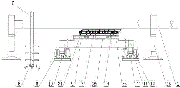
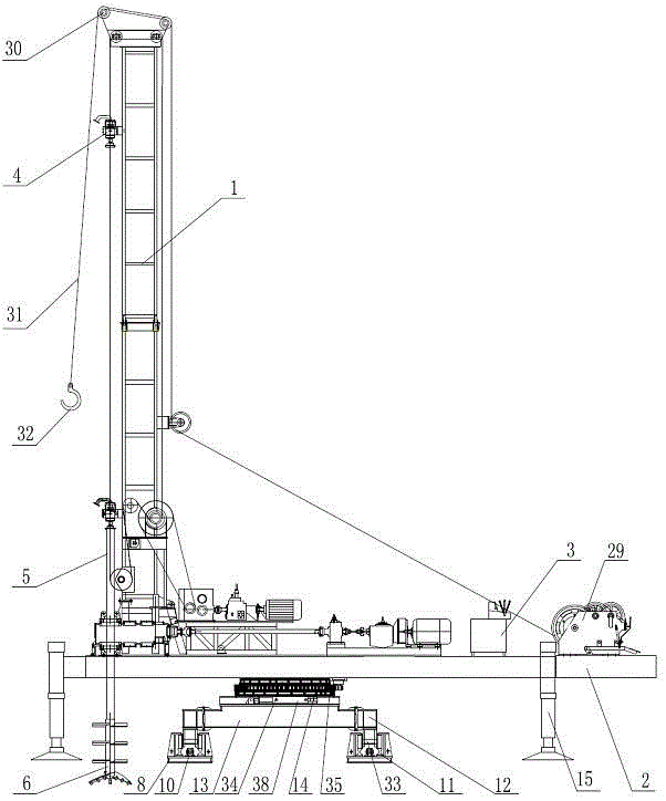
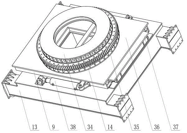
[0013] As shown in Figure 1, the steel cement-soil mixing pile machine with longitudinal movement mechanism of the present invention includes a tower frame 1, an upper chassis 2, a lower chassis 13, a hydraulic power system 3, a drill bit 6, a rotary mechanism 14, a longitudinal displacement mechanism 9, Lateral displacement mechanism 8.

[0014] The tower 1, the hydraulic power system 3 and the drill bit 6 are installed on the upper chassis 2, and the upper chassis 2 is fixedly connected to the upper connecting plate 34 on the upper part of the slewing mechanism 14, and the slewing mechanism 14 is fixedly connected to the longitudinal displacement mechanism through the lower connecting plate 35 9 upper part, the longitudinal displacement mechanism 9 is fixedly connected on the lower chassis 13 through the upper sliding box 36 and the lower sliding bo...


PUM


Abstract

The invention discloses a section steel soil cement mixing pile with a longitudinal moving mechanism, comprising a tower, an upper chassis, a lower chassis, a hydraulic power system, a drilling bit, a revolving mechanism, a longitudinal displacement mechanism and a transverse displacement mechanism. The upper chassis can rotate relative to the longitudinal displacement mechanism through the revolving mechanism, and the lower chassis can move linearly in a reciprocating manner on the transverse displacement mechanism through a transverse displacement oil cylinder. An upper sliding box of the longitudinal displacement mechanism is fixedly connected with the revolving mechanism, a lower sliding box of the longitudinal displacement mechanism is fixedly connected with the lower chassis, the upper sliding box is sleeved on the exterior of the lower sliding box, longitudinal moving oil cylinders are arranged at the two sides of the upper sliding box, and one ends of the longitudinal moving oil cylinders are hinged with the upper sliding box, and the other ends of the longitudinal moving oil cylinders are hinged with the lower chassis. The lower chassis is fixedly connected with the transverse displacement mechanism through bolts, a winch is mounted on the upper chassis, and a pulley block is mounted on the tower. The upper chassis and the lower chassis can move linearly and longitudinally in a reciprocating way through the longitudinal moving oil cylinders, so that the drilling bit can be accurately positioned, the transportation is facilitated, section steel can be conveniently hoisted, and the production efficacy is improved favorably.

Description

technical field [0001] The invention relates to a steel cement-soil mixing pile driver with a longitudinal movement mechanism, which belongs to the technical field of construction machinery equipment. Background technique [0002] The steel-cement-soil mixing pile machine is a kind of construction pile machinery equipment used for soft foundation treatment. The steel-cement-soil mixing pile machine drills to a certain depth on the soft ground site, and at the same time sprays cement-based strengthening agent at the drill bit. Repeated mixing and stirring with the foundation soil, overlapping construction is adopted between the construction units, and then the steel or steel plate is inserted as the stress reinforcing material before the cement-soil mixture is hardened, until the cement is hardened, a road with a unique structure is formed. A continuous and complete underground wall without joints with certain strength and rigidity. It is widely used in foundation reinforcem...

Claims


Application Information

Patent Timeline
Patent Type & Authority Applications(China)
IPC IPC(8): E02D5/46
Inventor 陈腊根
Owner WUHAN TIANBAO ENG MACHINERY
Features
  • R&D
  • Intellectual Property
  • Life Sciences
  • Materials
  • Tech Scout
  • Unparalleled Data Quality
  • Higher Quality Content
  • 60% Fewer Hallucinations
Learn More