Hydraulic switching valve

A technology of hydraulic switch and ball valve, which is applied in the direction of borehole/well valve device, borehole/well parts, earthwork drilling and production, etc. Small risk control, reasonable and compact structure

Active Publication Date: 2013-06-12
PETROCHINA CO LTD
View PDF5 Cites 14 Cited by
  • Summary
  • Abstract
  • Description
  • Claims
  • Application Information

AI Technical Summary

Problems solved by technology

[0005] In view of the technical problem that the existing downhole pitching control switching valve described in the background technology cannot realize the connection to the upper section after closing the lower section, the purpose of the present invention is to provide a hydraulic switching valve. The liquid flow in the shaft can be slowly discharged to the annulus of the oil jacket through the pressure relief hole and the outer circulation hole, without forming the "dead space" mentioned in the background technology, so that the mandrel can be further pushed down until the internal and external circulation Holes are fully connected

Method used


Image

  • Hydraulic switching valve
  • Hydraulic switching valve
  • Hydraulic switching valve

Examples


Embodiment Construction

[0038] In order to disclose the purpose, technical means and technical effects of the present invention more completely and clearly, the following is a detailed description, and please refer to the accompanying drawings and component numbers.

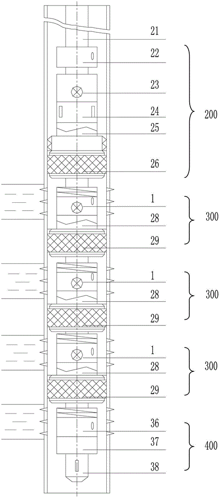
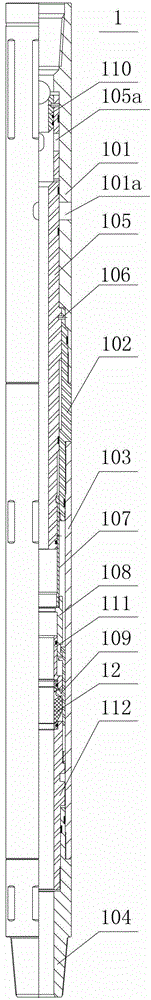
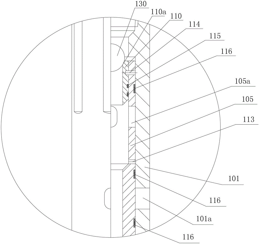
[0039] The invention provides a reasonable and compact hydraulic switch valve, such as figure 2 As shown, because of its long axial dimension, in order to clearly reflect the structure of each part, the figure 2 The part of the ball seat sleeve and the ball valve assembly are respectively enlarged as shown in image 3 and Figure 4 shown. Please refer to the following Figure 2 ~ Figure 4 , the hydraulic switching valve 1 of the present invention is connected to the downhole test pipe string, and is a multi-layer hollow tubular body, which has an outer layer, a middle layer and an inner layer in the radial direction, and the outer layer is connected from top to bottom in the axial direction There are an upper joint 101, an interme...


PUM


Abstract

The invention relates to a hydraulic switching valve connected to an underground testing tubular column. The hydraulic switching valve is a hollow tube body and is provided with an outer layer, an intermediate layer and an inner layer, wherein an upper joint, an intermediate joint, a ball valve outer barrel and a lower joint are arranged on the outer layer in the axial direction; the intermediate layer is provided with a slideable hollow mandrel fixed on the intermediate joint through a mandrel shear pin; a connecting claw, a connecting pup joint, an upper seat ring and a lower seat ring are further arranged at the lower end of the mandrel; two parallel grooves are formed in the side wall of the upper seat ring, two strip-shaped motion arms are respectively embedded into the two parallel grooves, and the top ends of the motion arms are buckled with the bottom end of the connecting pup joint; a ball seat sleeve body of which the top end can be clamped and sealed by a shot ball is arranged at the upper part of the mandrel, in the inner layer; a ball valve assembly is arranged in the upper seat ring, as well as the lower seat ring, in the inner layer, and is provided with an upper ball seat, a lower ball seat and a ball valve combined into the two ball seats, a seat spring is arranged between the ball valve and the upper ball seat, and the ball valve is matched with a bulged operation end of each motion arm; an upper joint is provided with an outer circulation hole; and the mandrel is provided with an inner circulation hole and a pressure release hole positioned between the inner circulation hole and the outer circulation hole.

Description

technical field [0001] The invention relates to a downhole tool for oil and gas well testing, in particular to a hydraulic switch valve. Background technique [0002] In the oil (gas) well, there are multiple perforated intervals that need to obtain oil test data separately, so layered oil test is required. The traditional layered oil testing method uses lower bridge plugs or cement plugs to seal the tested layers, and then goes back to the upper layer layer by layer for oil testing. Its disadvantages are that the pipe strings and bridge plugs (or cement injection plugs) are lowered many times, the construction period is long, the speed is slow, the cost is high, and the oil and gas layers are easily polluted. [0003] US Patent No. 2006 / 0207764 discloses an example of a multi-layer test, injection, production system. This patent relates to an assembly that enables multiple destination layers to be tested consecutively. The assembly includes a plurality of valves, and eac...

Claims


Application Information

Patent Timeline
Patent Type & Authority Applications(China)
IPC IPC(8): E21B34/08
Inventor 张友义孟庆昆刘新云王向东胡贵
Owner PETROCHINA CO LTD
Why Eureka
Try Eureka