Aerial bare cable utilizing microform sensing optical unit for temperature measurement and strain sensing

A technology for sensing light and micro shapes, which is applied in the fields of cables, overhead bare wires and submarine cables, can solve the problems of low sensitivity and poor real-time performance of optical fiber distributed sensing, and achieve the effect of real-time response embedding process, high sensitivity and improved sensitivity

Inactive Publication Date: 2013-06-12
江苏通光海洋光电科技有限公司
View PDF4 Cites 2 Cited by
  • Summary
  • Abstract
  • Description
  • Claims
  • Application Information

AI Technical Summary

Problems solved by technology

Therefore, the optical fiber distributed sensing technology using conventional communication optical cables or optical units has low sensitivity and poor real-time performance. Obviously, it is not ideal to use conventional communication optical cables as distributed sensing.

Method used


Image

  • Aerial bare cable utilizing microform sensing optical unit for temperature measurement and strain sensing
  • Aerial bare cable utilizing microform sensing optical unit for temperature measurement and strain sensing
  • Aerial bare cable utilizing microform sensing optical unit for temperature measurement and strain sensing

Examples


Embodiment 1

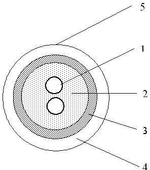
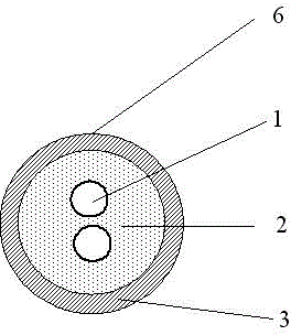
[0028] Such as figure 1 with 2 The micro-shaped sensing optical unit shown is embedded in the inside or outside of the cable. It includes a micro-shaped sensing optical unit body. The micro-shaped sensing optical unit body includes a sensing optical fiber 1, and the sensing optical fiber 1 is covered with a sealed Stainless steel tube 3, the stainless steel tube 3 is filled with water-blocking fiber paste 2; the number of sensing optical fibers 1 is 1 or 2 or more, and the range of the excess length of the fiber in the stainless steel tube 3 is: 0≤excess length <0.03% . The stainless steel tube 3 may also be covered with a sheath 4.

[0029] The micro-sensing light unit is manufactured by special equipment. The protective tube of the micro-sensing light unit is usually made of a stainless steel tube 3 with a thickness of 0.15mm-0.2mm through molding, laser welding, and sizing drawing. The protective tube is formed on the stainless steel tube 3. Input the optical fiber 1 for sens...

Embodiment 2

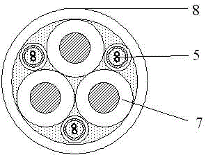
[0031] Such as image 3 with 4 As shown, the cable for temperature measurement using the micro-shaped optical sensing unit described in Example 1. The cable includes a cable conductor core 7 and a cable outer sheath 8, and also includes a micro-sensing optical unit and a stainless steel tube of the micro-sensing optical unit 3 is wrapped with a sheath 4, and the miniature sensing light unit 5 with the sheath and the cable conductor core 7 are simultaneously twisted inside the cable or wound around the outer sheath 8 of the cable. In this embodiment, due to the insulation requirements of the cable, a sheathed micro-shaped sensor optical unit 5 is generally used. image 3 It is a schematic diagram of the cable structure for detecting the internal temperature of the cable. The sensor light unit 5 with a sheath can be one or more. image 3 In the middle are 3 sheathed sensing light units 5 and the cable core wires are twisted synchronously. Figure 4 It is a schematic diagram of the ...

Embodiment 3

[0033] Such as Figure 5 As shown, the duct optical cable for strain sensing using the micro-sensing optical unit described in Embodiment 1. The duct optical cable includes a conventional communication optical unit 9 and an optical cable outer sheath 11, and also includes a micro-sensing optical unit and a micro-sensing optical unit The miniature sensor optical unit 6 without a sheath and without a sheath and the conventional communication optical unit 9 are simultaneously twisted inside the pipe optical cable. The outer diameter of the micro-shaped sensing optical unit 6 without a sheath is matched with the gap of the conventional communication optical unit 9 so that it is tangent to the circular track formed by the conventional communication optical unit 9.

[0034] Such as Image 6 As shown, the buried optical cable for strain sensing using the micro-shaped sensing optical unit described in Embodiment 1. The buried optical cable includes a conventional communication optical uni...


PUM

PropertyMeasurementUnit
thicknessaaaaaaaaaa

Abstract

The invention relates to a microform sensing optical unit embedded into the interior or the exterior of cable. The microform sensing optical unit comprises a microform sensing optical unit body and is characterized in that the microform sensing optical unit body comprises optical fibers for sensing, sealed stainless steel pipes are coated on the exteriors of the optical fibers for sensing, waterproof fiber paste is filled inside the stainless steel pipes, the number of the optical fibers for sensing is one or two or more, and the optical fiber extra lengths inside the stainless steel pipes are larger than or equal to 0 and smaller than 0.03 percent. Further disclosed are an embedded type electric cable, optical cable, aerial bare cable and submarine cable. The structure is applied to the electric cable, the optical cable, the aerial bare cable and the submarine cable. The microform sensing optical unit is high in sensitivity for measured information of the external world, real-time in response of temperature and strain, simple in embedded process, free of changing original properties of the optical cable and the electric cable and capable of responding temperature changes in a real-time mode. The smaller optical fiber extra lengths of optical fibers inside the pipes shorten an area of a stress-strain window of the optical fibers. Sensitivity of stress-strain reaction to the external world of the optical fibers is improved, and the microform sensing optical unit can be embedded into the appropriate portions of the optical cable and the electric cable without changing the original structure and performance of the optical cable and the electric cable.

Description

Technical field [0001] The invention relates to distributed online measurement and sensing of optical fibers, in particular to a micro-shaped sensing optical unit and cables, optical cables, overhead bare wires and submarine cables using the structure embedded. Background technique [0002] Optical fiber sensing technology is a new type of sensing technology that uses light as the carrier and optical fiber as the medium to sense external information. Using the various characteristics of optical fibers, optical fibers can be made into various sensors, but they are distributed in space in a point-like manner. In addition to discontinuous measurement points, additional transmission lines (optical cables or cables) are also required. [0003] The distributed optical fiber measurement and sensing system can provide the measured information as a continuous function of the distance along the continuous length of the entire optical fiber with the change of the optical fiber length directio...

Claims


Application Information

Patent Timeline
Patent Type & Authority Applications(China)
IPC IPC(8): G01K11/32G01B11/16G01D5/26
CPCD07B1/145D07B2201/2096D07B2301/5577D07B2301/252D07B2301/259
Inventor 徐军黄俊华
Owner 江苏通光海洋光电科技有限公司
Why Eureka
Try Eureka