
Lenz's law demonstration device

A demonstration device and Lenz's law technology, applied in the field of Lenz's law demonstration device, can solve the problems of poor demonstration effect, troublesome assembly, inconvenient operation, etc., and achieve the effect of improving resource utilization, good demonstration effect, and easy disassembly

Inactive Publication Date: 2013-06-12
郑扬威 +1
View PDF10 Cites 1 Cited by
  • Summary
  • Abstract
  • Description
  • Claims
  • Application Information

AI Technical Summary

Problems solved by technology

The disadvantage of this kind of demonstration device is that it must be demonstrated in a fixed position, it is not convenient to walk around for demonstration, the demonstration effect is not obvious, and it is inconvenient to operate, and it is easy to touch the metal ring and cause it to rotate
Although many Lenz's law demonstrators have appeared one after another, some of them have good demonstration effects, but their structures are complicated, their cost is high, their use is inconvenient, and they are not easy to carry.
Although some are simple in structure and low in cost, the demonstration effect is not good, such as using copper tubes to demonstrate
The Chinese utility model patent with the authorized announcement number CN 202677681 U discloses a demonstration device of Lenz’s law. Two insulating tubes are vertically fixed on the base, and an insulating inner tube with a slightly smaller outer diameter is installed in one of the insulating tubes. A closed coil is fixed on the insulated inner tube, and a wallboard is installed vertically on the base behind the insulating tube, and a magnetic ring and a supporting plate are installed on the wallboard through a hinge. The device overcomes the disadvantages of the previous Lenz's law demonstration device that the demonstration effect is not obvious and bad, and has an intuitive demonstration effect, but the structure is complex, it is not easy to mass-produce, and it is not portable. When teachers need classroom demonstrations, it is troublesome to carry and assemble. Not suitable for teachers to walk around and demonstrate

Method used


Image

  • Lenz's law demonstration device
  • Lenz's law demonstration device
  • Lenz's law demonstration device

Examples


Embodiment 1

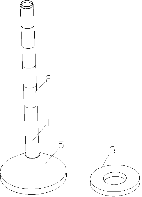
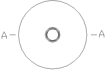
[0033] A demonstration device for Lenz's law, comprising a non-magnetic and non-conductive second cylinder 2 used as a comparative experiment, a non-magnetic metal ring 3, and at least one magnet is arranged above and / or below the second cylinder 2 4 constitute a whole experimental column, when more than two magnets 4 are provided, two adjacent magnets 4 are arranged at intervals through the support, and the metal ring 3 can slide on the entire experimental column, wherein each magnet 4 The north and south poles are in the same direction and are in the same length direction as the above-mentioned entire experimental column. The suit refers to an assembly in which the metal ring 3 is placed outside the entire experimental cylinder during demonstration, and when released, the metal ring 3 can move downwards along the cylinder under the action of gravity. Wherein the support member can be a non-magnetic, non-conductive long first cylinder 1, and the above-mentioned magnets 4 are ...

Embodiment 2

[0036] The difference between this embodiment and embodiment 1 is:

[0037] Wherein the support member is a non-magnetic, non-conductive short first cylinder 1, and one of the above-mentioned magnets 4 is integrally formed or embedded in the inside or one end of the first cylinder 1 to form a magnet cylinder combination unit, at least one section of the magnet cylinder The body assembly unit can be detachably connected in series to form a magnet cylinder assembly, and the center lines of the magnet 4 and the first cylinder 1 coincide. A Lenz's law demonstration device with this structure is easy to disassemble, easy to use, easy to carry, store and transport, and the size of the first cylinder 1 can be exactly the same, which not only has a simple structure but also facilitates mass production, reduces costs, and improves resource utilization. The demonstration is flexible, and magnet cylinder assemblies of different lengths can be assembled according to the needs to achieve a...

Embodiment 3

[0040] The difference between this embodiment and embodiment 1 is:

[0041]Wherein the support member is a non-magnetic, non-conductive short first cylinder 1, and one of the above-mentioned magnets 4 is arranged in the magnet placement hole 21 at one end of the first cylinder 1 to form a magnet cylinder combination unit, the first cylinder The other end of 1 is provided with a matching position, so that the end of the magnet placement hole 21 of one section of the first cylinder 1 can be tightly connected with the matching end of the other first cylinder 1, and at least one section of the magnet cylinder combination unit is detachable A magnet cylinder assembly is connected in series, and the center lines of the magnet 4 and the first cylinder 1 coincide. Wherein the matching position can be a size slightly smaller than the magnet placement hole 21, and can be tightly fitted with the matching position protrusion 22, in order to save material, the matching position concave hol...


PUM


Abstract

The invention discloses a Lenz's law demonstration device, which comprises a non-magnetic-conductive and non-electric-conductive second column body and a non-magnetic-conductive metal ring which are used for conducting a contrast experiment, wherein at least one magnet is arranged above or below the second column body; a spacing distance is arranged between every two adjacent magnets; the metal ring can be sleeved outside the magnet and the second column body in a sliding manner; and orientations of the south and north poles of each magnet are consistent and are the same as the length direction of the column body. The Lenz's law demonstration device disclosed by the invention has the advantages of simplicity in structure, convenience in use, good demonstration effect, more intuition, and easiness in batch production, detachability and visualization.

Description

[0001] technical field [0002] The invention relates to an electromagnetic induction phenomenon demonstration device, in particular to a Lenz law demonstration device. [0003] Background technique [0004] The traditional demonstration device of Lenz's law mainly consists of two metal rings fixed at both ends of a metal bar, one of which is closed and the other is open, and the concave groove at the center of gravity of the metal bar is supported by the thimble at the upper end of the bracket , can rotate around the thimble. The defect of this kind of demonstration device is that it must be demonstrated in a fixed position, which is not convenient for walking and demonstration, the demonstration effect is not obvious, and it is inconvenient to operate, and it is easy to touch the metal ring and cause it to rotate. Although numerous Lenz's law demonstrators have appeared successively, some of them have good demonstration effects, but their structures are complicated, thei...

Claims


Application Information

Patent Timeline
Patent Type & Authority Applications(China)
IPC IPC(8): G09B23/18
Inventor 郑扬威杜赧
Owner 郑扬威
Learn More