Self-adaptive dead time control

A technology of time and time difference, which is applied in the field of dead time control and can solve problems such as power loss

Active Publication Date: 2013-06-12
MAXIM INTEGRATED PROD INC
View PDF10 Cites 13 Cited by
  • Summary
  • Abstract
  • Description
  • Claims
  • Application Information

AI Technical Summary

Problems solved by technology

Power loss also occu...

Method used


Image

  • Self-adaptive dead time control
  • Self-adaptive dead time control
  • Self-adaptive dead time control

Examples


Embodiment Construction

[0034] The following description is merely exemplary in nature and is in no way intended to limit the disclosure, its application, or uses. For purposes of clarity, the same reference numbers will be used in the drawings to identify similar elements. As used herein, the phrase at least one of A, B, and C should be taken to mean a logical (A or B or C) using a non-exclusive logical or. It should be understood that steps within a method may be executed in different order without altering the principles of the present disclosure.

[0035] As used herein, the term module may refer to: an application-specific integrated circuit (ASCI); an electronic circuit; a combinational logic circuit; a field-programmable gate array (FPGA); a processor (shared, dedicated, or group) that executes code; Other suitable components of functionality; or a combination of some or all of the above components, such as part of a system on a chip; or the term module may include application specific integr...


PUM


Abstract

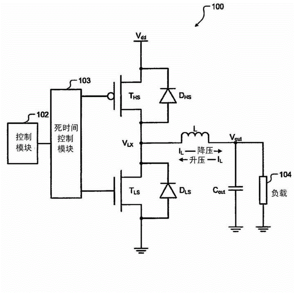
The invention relates to self-adaptive dead time control. A DC-DC converter comprises a first transistor and a second transistor which are in series connection between a power voltage and the ground and are driven by PWM pulses. A connecting point between the two transistors is connected to an inductor that is in series connection with a load. A first timing module is used for determining a first time difference between a first edge of a first signal at the connecting point and a first edge of a second signal at a control terminal of the first transistor. A second timing module is used for determining a second time difference between a second edge of the first signal and a second edge of the second signal. The first edge and the second edge of the second signal respectively corresponds to a first edge and a second edge of one pulse among the PWM pulses. A delay module is used for delaying the first edge and the second edge of the second signal respectively based on the first time difference and the second time difference.

Description

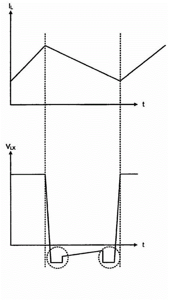
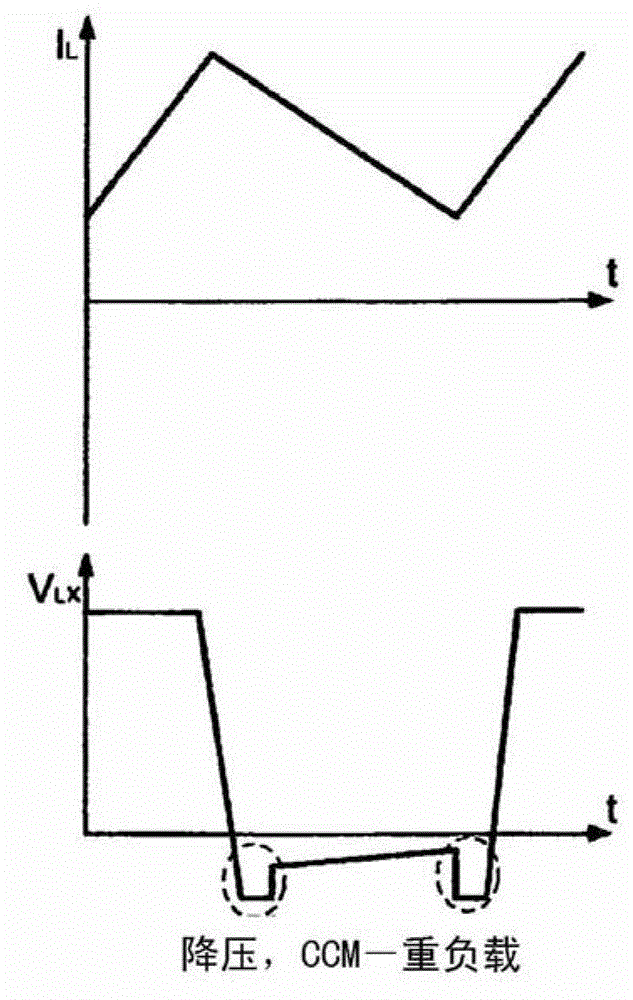
[0001] Cross References to Related Applications [0002] This application is based on U.S. Provisional Application No. 61 / 567938, filed December 7, 2011. The disclosure of the above application is hereby incorporated by reference in its entirety. technical field [0003] The present disclosure relates generally to DC-DC voltage converters, and more particularly to dead time control in DC-DC voltage converters. Background technique [0004] The background description provided herein is for the purpose of generally presenting the context of the disclosure. The work of the presently named inventors, to the extent described in this Background section, and which at the time of filing would not otherwise be considered prior art description, is neither expressly nor implicitly admitted to be part of the present disclosure existing technology. [0005] now refer to Figure 1A and 1B , shows a DC-DC converter (hereinafter, converter) 100 . exist Figure 1A Among them, the conver...

Claims


Application Information

Patent Timeline
IPC IPC(8): H02M3/155
CPCH02M1/38H02M3/1588Y02B70/10G05F3/08H02M3/158
Inventor S·M·扎克B·A·米瓦
Owner MAXIM INTEGRATED PROD INC
Why Eureka
Try Eureka