Light source device

A light source device and light source technology, which are applied to lighting devices, components of lighting devices, optical elements used to change the spectral characteristics of emitted light, etc., can solve problems such as slow filter switching speed

Active Publication Date: 2013-06-12
OLYMPUS CORP
View PDF8 Cites 7 Cited by
  • Summary
  • Abstract
  • Description
  • Claims
  • Application Information

AI Technical Summary

Problems solved by technology

[0007] However, although the light source device disclosed in JP 2006-75239 A can achieve normal observation and special light observation separately, it has a problem that the filter switching speed is slow due to the filter moving mechanism.

Method used


Image

  • Light source device
  • Light source device
  • Light source device

Examples


no. 1 Embodiment approach )

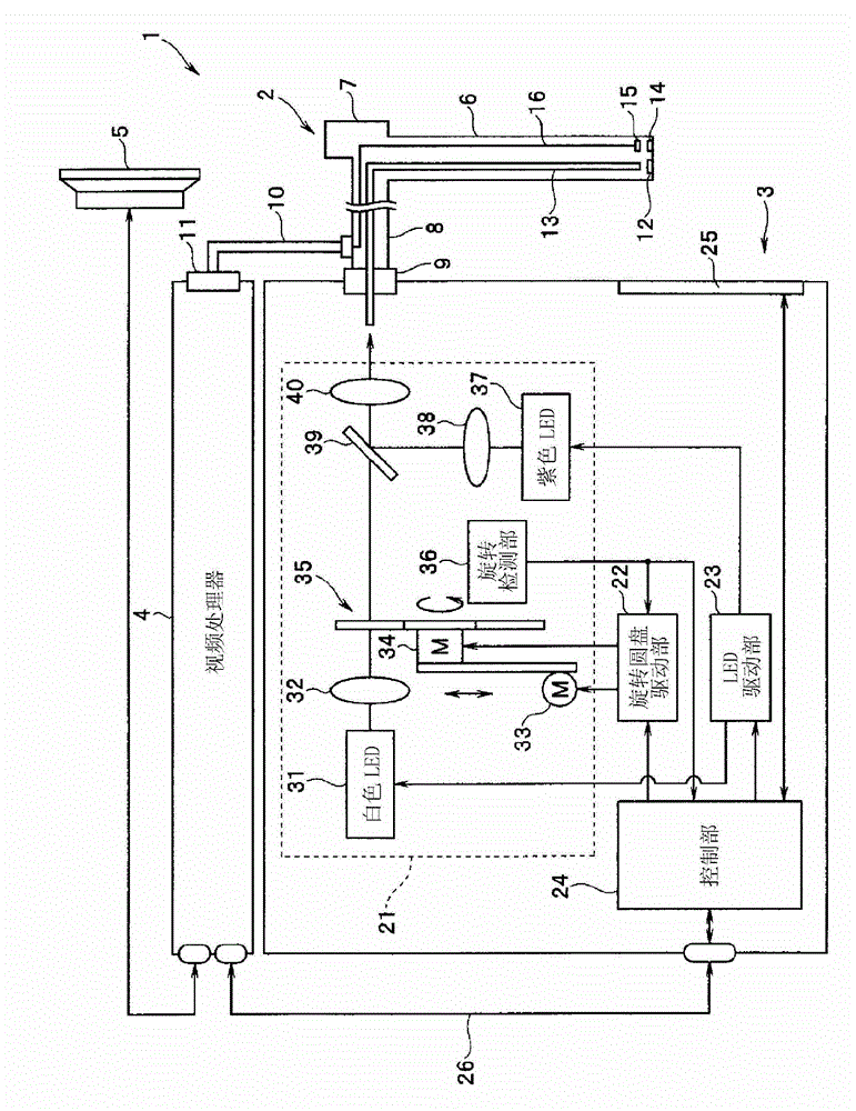
[0032] First, based on figure 1 The configuration of an endoscope system including the light source device according to the first embodiment of the present invention will be described.

[0033] figure 1 It is a diagram showing the configuration of an endoscope system including the light source device according to the first embodiment of the present invention.

[0034] Such as figure 1 As shown, an endoscope system 1 is configured to include an endoscope 2 that images an object inside a living body and outputs an imaging signal, and a light source that supplies illumination light to the endoscope 2 for illuminating the object. The device 3 , the video processor 4 that converts the imaging signal output from the endoscope 2 into a video signal and outputs it, and the display 5 that displays an image corresponding to the video signal output from the video processor 4 .

[0035] The endoscope 2 is configured to include an elongated insertion portion 6 capable of being inserted ...

no. 2 Embodiment approach

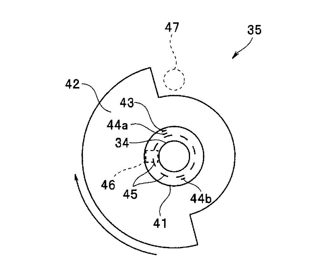
[0093] The structure of the light source device of the second embodiment uses a rotating disk 35 a instead of the rotating disk 35 of the first embodiment.

[0094] Figure 11 It is a figure which shows the structure of the rotating disk of 2nd Embodiment.

[0095] Such as Figure 11 As shown, the rotating disc 35a has a filter 42a. The filter 42 of the first embodiment has a shape obtained by combining two semicircles with different diameters, but the filter 42 a of the present embodiment has a shape obtained by alternately combining two 1 / 4 circles with different diameters. In addition, filter position detection screens 44 c and 44 d for detecting the rotational position of such a filter 42 a are added to the disk main body 41 .

[0096] The rotary motor 34 rotates the rotary disk 35 a at a constant speed of 15 Hz which is half of that of the first embodiment under the control of the rotary disk drive unit 22 .

[0097] According to the light source device 3 of this embo...

no. 3 Embodiment approach )

[0100] Next, a third embodiment will be described.

[0101] The structure of the light source device of the third embodiment is substantially the same as that of the first embodiment, and only the different structures will be described.

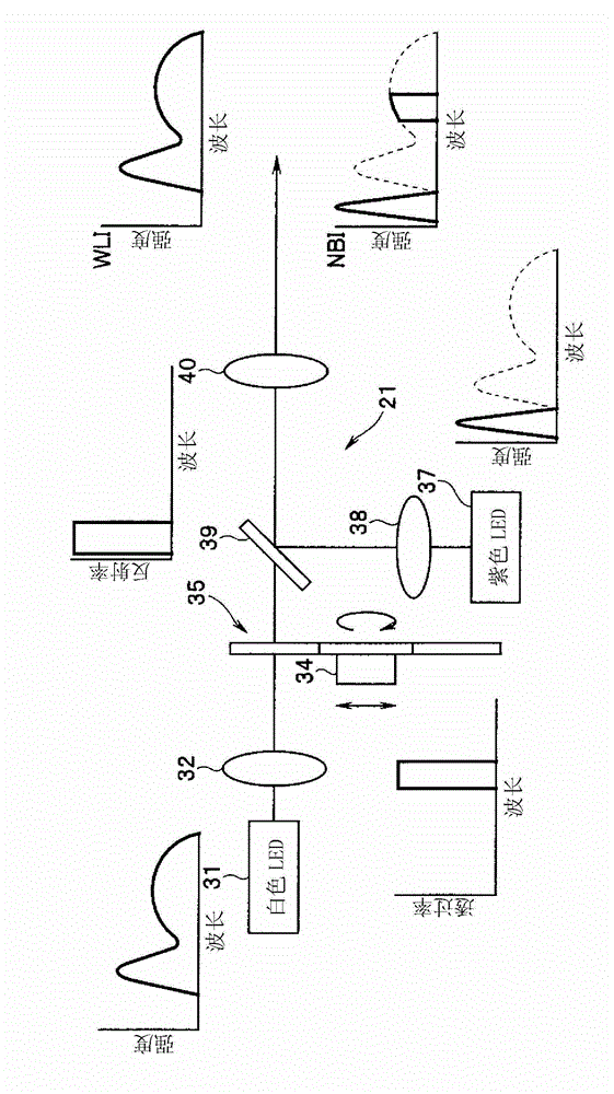
[0102] Figure 12 It is a figure which shows the structure of the optical system of 3rd Embodiment. In addition, instead of the rotating disk 35, the structure which uses the rotating disk 35a of 2nd Embodiment may be used.

[0103] In this embodiment, the purple LED 37 is turned on not only during narrow-band observation but also during normal observation, specifically, normal observation in normal observation mode and normal observation in dual mode. The LED drive unit 23 outputs a drive signal for lighting the purple LED 37 to the purple LED 37 during normal observation under the control of the control unit 24 . However, the intensity of the purple LED 37 during normal observation is lower than the intensity during narrowband observatio...


PUM


Abstract

A light source device (3) has a white LED (31) that emits light comprising a first wavelength band and a second wavelength band, a violet LED (37) that emits light of a third wavelength band, and a rotating disc (35) that has a filter (42) which passes light of the first wavelength band when inserted in the light path of the white LED (31). The light source device (3) also has a rotating disc-driver (22) that changes the position of the rotating disc (35), so that the filter (42) is withdrawn from the light path of the light emitted from the white LED (31) when the white-light imaging mode is selected; the filter (42) is inserted continuously in the light path of the light emitted from the white LED (31) when the narrow-band imaging mode is selected; and the filter (42) is inserted intermittently in the light path of the light emitted from the white LED (31) when the twin mode are selected.

Description

technical field [0001] The invention relates to a light source device, in particular to a light source device capable of performing common observation and special light observation at the same time. Background technique [0002] Conventionally, a light source device capable of special light observation such as narrow-band observation (NBI) capable of observing the vicinity of the mucosal surface layer of living tissue in addition to general observation (WLI) using white illumination has been developed (for example, refer to Japanese Patent Laid-Open 2006-75239 Bulletin). [0003] In this light source device, by including a turntable with a plurality of optical filters, and disposing the optical filter corresponding to the observation mode in the optical path of the xenon lamp, mode switching between normal observation and special light observation is realized. [0004] In addition, in recent years, light source devices using LEDs have been developed in the field of endoscop...

Claims


Application Information

Patent Timeline
Patent Type & Authority Applications(China)
IPC IPC(8): A61B1/06A61B1/00
CPCA61B1/0638A61B1/0646A61B1/00186A61B1/0669A61B1/0684F21V9/20A61B1/0655
Inventor 矢部雄亮
Owner OLYMPUS CORP
Why Eureka
Try Eureka