Heavy-load walking beam lifting hydraulic control device

A control device and hydraulic technology, applied in the field of hydraulic control, can solve the problems of large power loss, complicated and complicated pipeline layout, etc., and achieve the effect of low power and simplified circuit and pipeline layout.

Active Publication Date: 2015-05-27
KEDA INDUSTRIAL GROUP CO LTD
View PDF9 Cites 0 Cited by
  • Summary
  • Abstract
  • Description
  • Claims
  • Application Information

AI Technical Summary

Problems solved by technology

However, the hydraulic control devices currently used in the industry use balance valves to balance the weight of the moving beam, and use double-acting hydraulic cylinders to control the lifting action of the moving beam. The layout is complicated and the power loss is large

Method used


Image

  • Heavy-load walking beam lifting hydraulic control device
  • Heavy-load walking beam lifting hydraulic control device
  • Heavy-load walking beam lifting hydraulic control device

Examples


Embodiment Construction

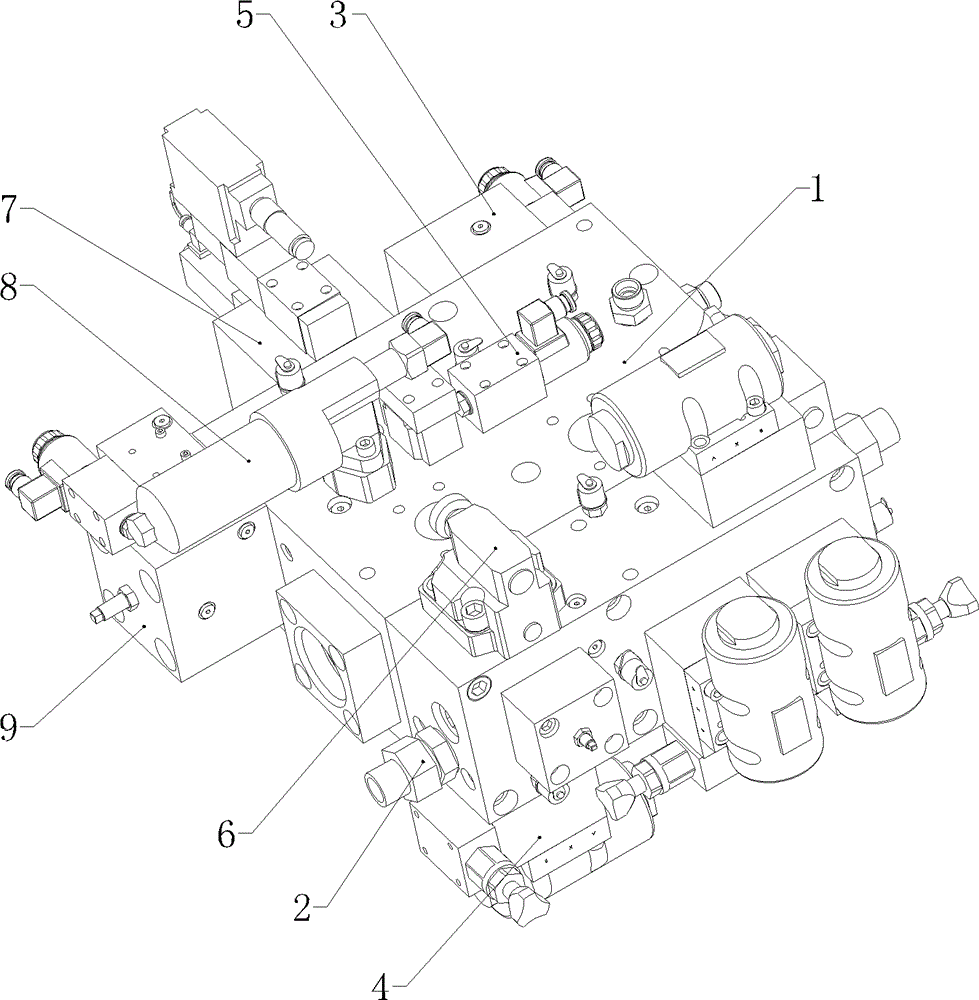
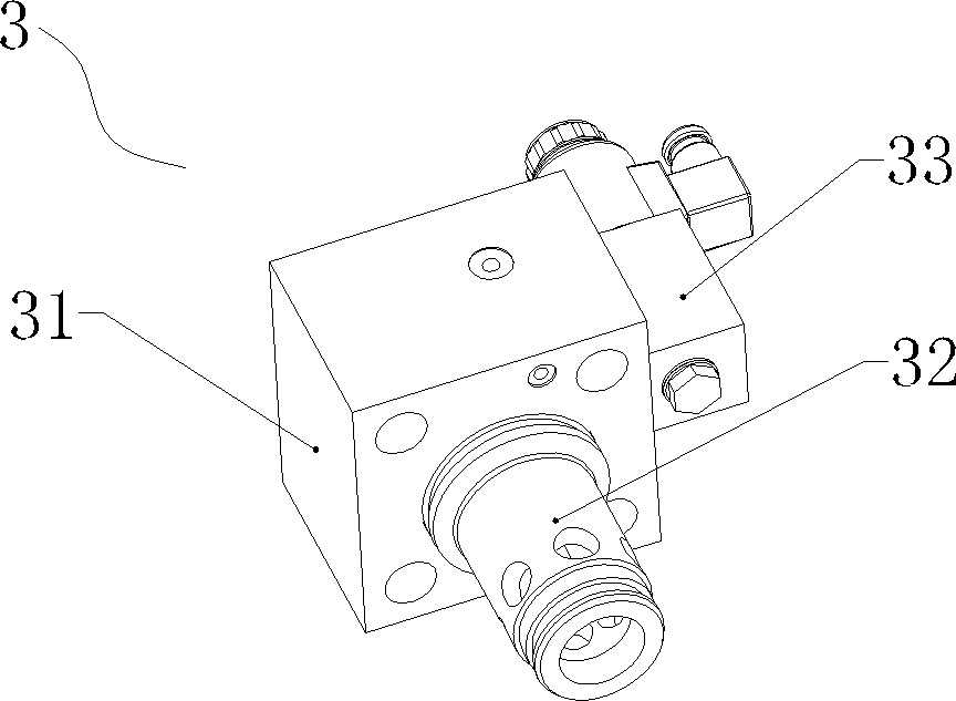
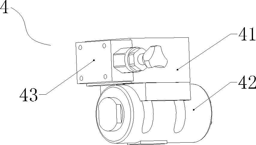
[0018] Such as Figure 1 to Figure 4 As shown, the heavy-duty moving beam lifting hydraulic control device of the present invention is mainly composed of several single-acting hydraulic cylinders (not shown in the figure) and an oil circuit block 1 . A number of hydraulic components are installed on the oil block 1, and these hydraulic components are mainly composed of a number of detachable high-pressure welded steel pipe joints 2, an oil inlet control unit 3, a number of safety locking units 4, an electromagnetic reversing valve 5, a safety valve 6, It consists of a high-response dynamic proportional cartridge valve 7, a precision high-pressure filter 8 and a dynamic oil return control unit 9. The piston rod ends of the several single-acting hydraulic cylinders are connected with the moving beam of the metal extruding machine to drive the moving beam for vertical lifting. The oil circuit of each single-acting hydraulic cylinder is connected with a detachable high-pressure w...


PUM


Abstract

The invention discloses a heavy-load walking beam lifting hydraulic control device. The heavy-load walking beam lifting hydraulic control device comprises a plurality of single-action hydraulic cylinders and an oil way block, wherein the oil way block is provided with a plurality of hydraulic elements; and the plurality of hydraulic elements comprise at least one steel tube joint, an oil inlet control unit, a safety interlocking unit the quantity of which is same with that of the steel tube joint, an electromagnetic directional valve, a safety valve, a high respondence dynamic proportion cartridge valve, a precision high-pressure filter and a dynamic oil return control unit. According to the invention, a hydraulic control loop and a pipeline are simplified in arrangement, the lifting movement of a walking beam is driven by hydraulic power, the lowering motion of the walking beam takes self weight as a power source, the lifting movement requires lower power, and the energy-saving purpose is achieved.

Description

technical field [0001] The invention belongs to the technical field of hydraulic control, and in particular relates to a heavy-duty movable beam lifting hydraulic control device mainly used in a vertical inner cavity metal extrusion molding machine. Background technique [0002] An existing vertical inner cavity metal extrusion molding machine (such as the vertical inner cavity metal extrusion molding machine of Keda Company) has a large mass of moving beam and a long stroke, and the lifting action of the moving beam is required to be fast, stable, safe and reliable. There are strict requirements on handling performance. However, the hydraulic control devices currently used in the industry use balance valves to balance the weight of the moving beam, and use double-acting hydraulic cylinders to control the lifting action of the moving beam. The layout is complicated and the power loss is relatively large. Contents of the invention [0003] The purpose of the present inven...

Claims


Application Information

Patent Timeline
Patent Type & Authority Patents(China)
IPC IPC(8): B21C31/00
Inventor 张昭政何浩波陈伟俊崔智敏
Owner KEDA INDUSTRIAL GROUP CO LTD
Why Eureka
Try Eureka