
Integrated circuit (IC) line welding machine

A welding machine and circuit technology, applied in welding equipment, auxiliary welding equipment, welding/cutting auxiliary equipment, etc., can solve problems such as narrow applicability, easy failure, and danger to workers, and achieve the effect of automatic production

Inactive Publication Date: 2013-06-19
SIP GOLDWAY TECH
View PDF10 Cites 0 Cited by
  • Summary
  • Abstract
  • Description
  • Claims
  • Application Information

AI Technical Summary

Problems solved by technology

At present, the general welding machine generally needs to manually remove the welded part from the welded part holding device after the welding process is completed. This method is time-consuming and dangerous to the staff. The manipulator is used to pick up parts, but because the production of the manipulator is more complicated, and it is also prone to failure, the applicability is narrow

Method used


Image

  • Integrated circuit (IC) line welding machine
  • Integrated circuit (IC) line welding machine
  • Integrated circuit (IC) line welding machine

Examples


Embodiment Construction

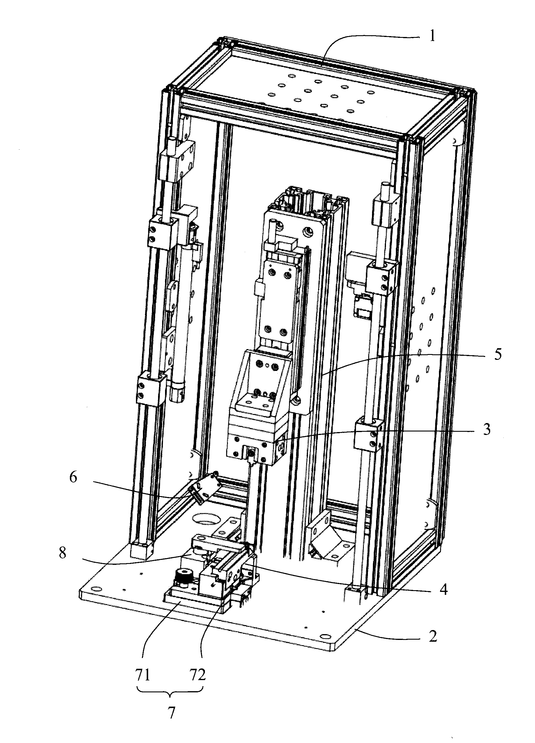
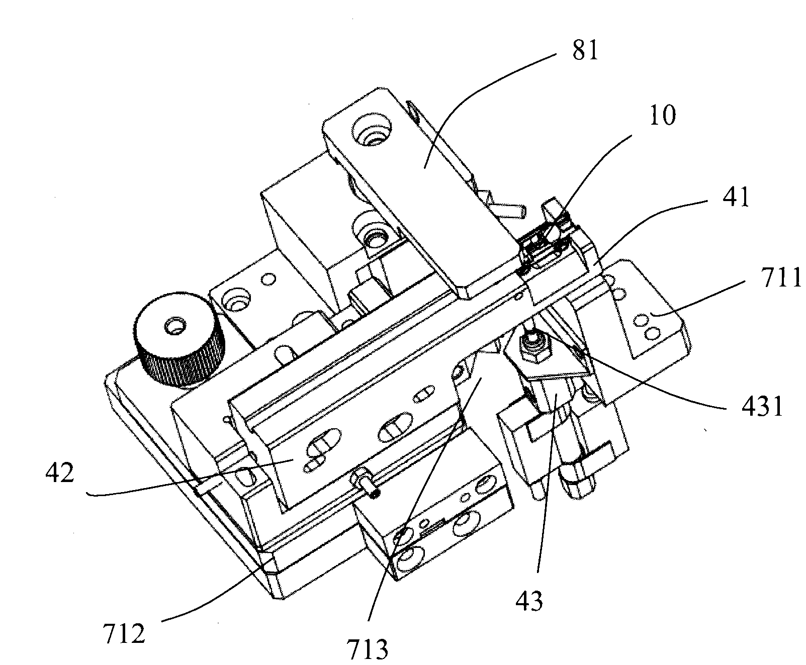
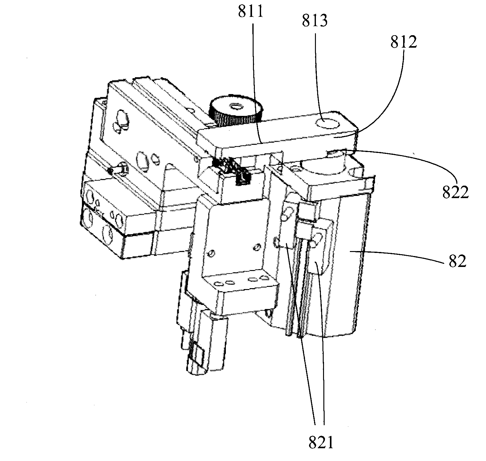
[0022] See figure 1 An IC circuit welding machine includes a bracket 1, a base 2 arranged in the bracket 1, a welding piece clamping device 4 and a welding piece clamping device 8 fixed on the base 2, and a welding piece above the welding piece clamping device 4. The head heating device 3 , the rail device 5 that drives the welding head heating device 3 to move up and down, and the observation piece 6 . The weldment clamping device 4 is used to clamp the weldment 10, while the weldment clamping device 8 is used to compress the weldment 10, so as to ensure that the weldment 10 will not pop out from the weldment clamping device 4 during the welding process Or displacement, affect the welding effect and welding time, realize the purpose of smooth welding and ensure the welding quality, the welding head heating device 3 welds the welding piece 10 clamped on the welding piece holding device 4 through the welding head 31 arranged on it, so The observation piece 6 is installed on th...


PUM


Abstract

The invention relates to an integrated circuit (IC) line welding machine which comprises a support, a base arranged in the support, a weld part holding device fixed on the base, and a weld head arranged above the weld part holding device. The weld head is used for welding a weld part clamped on the weld part holding device which comprises a clamping portion. The clamping portion comprises a bottom surface, clamping arms and a clamping cavity, wherein the bottom surface upward extends to form the clamping arms which are used for clamping the weld part, and the clamping cavity is formed by the bottom surface and the clamping arms. A dismounting hole is formed in the bottom surface. A movable rod is arranged below the dismounting hole and can vertically move. When the movable rod moves upward, the movable rod penetrates the dismounting hole. Due to the fact that the dismounting hole is formed in the bottom surface of the clamping portion, the movable rod is arranged below the dismounting hole and can vertically move, and movable rod penetrates the dismounting hole, when the movable rod moves upward, the weld part can be ejected by the movable rod after welding is finished so that the weld part is dismantled, and therefore automatic production is achieved.

Description

technical field [0001] The invention relates to an IC circuit welding machine. Background technique [0002] Welding is a common technique for joining metal parts by passing metal alloys under the action of heat. In this case, the metal alloy (also called solder) reaches a melting temperature which is lower than the melting temperature of the metal parts to be joined. During soldering, molten solder flows between two metal parts. Under favorable conditions, a strong, tight, corrosion-resistant, electrically and thermally conductive connection is obtained between the solder and the metal. [0003] When the era entered the era of mechanized production, in terms of welding technology, in order to increase welding output and reduce welding time, welding machines were born. The current welding machine generally includes a bracket, a base arranged in the bracket, a welding piece clamping device fixed on the base for clamping the welding piece, and a welding head for the welding...

Claims


Application Information

Patent Timeline
IPC IPC(8): B23K37/04
Inventor 沈皓然
Owner SIP GOLDWAY TECH
Learn More