
Motor vehicle logo

A technology for motor vehicles and car logos, applied to vehicle parts, point light sources, lighting and heating equipment, etc., can solve the problems of increased difficulty and cost of assembly, difficult operation, thick components, etc., to achieve delicate and guaranteed luminous effects The effect of weather resistance

Active Publication Date: 2013-06-19
BYD CO LTD
View PDF7 Cites 25 Cited by
  • Summary
  • Abstract
  • Description
  • Claims
  • Application Information

AI Technical Summary

Problems solved by technology

However, the disclosed long rectangular thin light guide plate and light-emitting diodes are arranged on one side of the integrated board, and it is not suitable to apply to the car logo with other car logo patterns in the closed ring, which will violate the design of the car logo due to changing the shape and structure of the car logo. The original intention of the icon design, secondly, the power cord is required to be connected to the power supply through the low wall, and the bottom plate needs to be sealed with a waterproof rubber ring to ensure its airtightness. It is difficult to operate in actual product manufacturing, which increases the difficulty and cost of assembly.
[0005] The disadvantage of the existing technology is that although some car logos can achieve the luminous effect of forming a halo on the edge of the car logo, the brightness is too low and the thickness of the components is relatively thick
In addition, through the design of the light-receiving surface structure and using the principle of refraction to achieve the effect of emitting light from the raised characters of the car logo, it is not suitable for the lighting of the closed car logo pattern, and a waterproof rubber ring is required to ensure its tightness, which is very difficult in actual product manufacturing. Difficult to operate, increasing the difficulty and cost of assembly

Method used


Image

  • Motor vehicle logo
  • Motor vehicle logo

Examples


Embodiment Construction

[0014] Embodiments of the present invention are described in detail below, examples of which are shown in the drawings, wherein the same or similar reference numerals designate the same or similar elements or elements having the same or similar functions throughout. The embodiments described below by referring to the figures are exemplary only for explaining the present invention and should not be construed as limiting the present invention.

[0015] In describing the present invention, it should be understood that the terms "center", "longitudinal", "transverse", "upper", "lower", "front", "rear", "left", "right", " The orientations or positional relationships indicated by "vertical", "horizontal", "top", "bottom", "inner" and "outer" are based on the orientations or positional relationships shown in the drawings, and are only for the convenience of describing the present invention and Simplified descriptions, rather than indicating or implying that the device or element refe...


PUM


Abstract

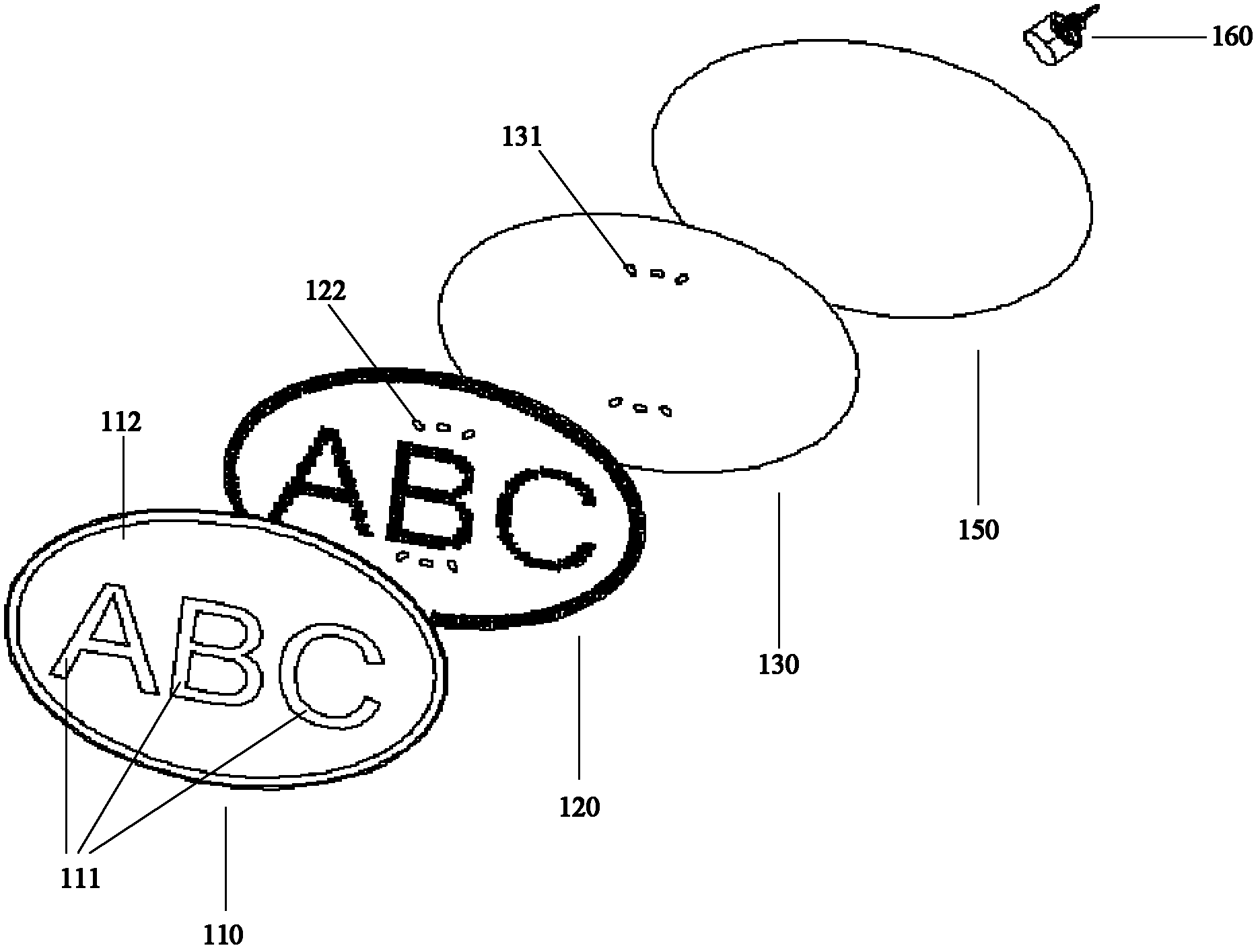
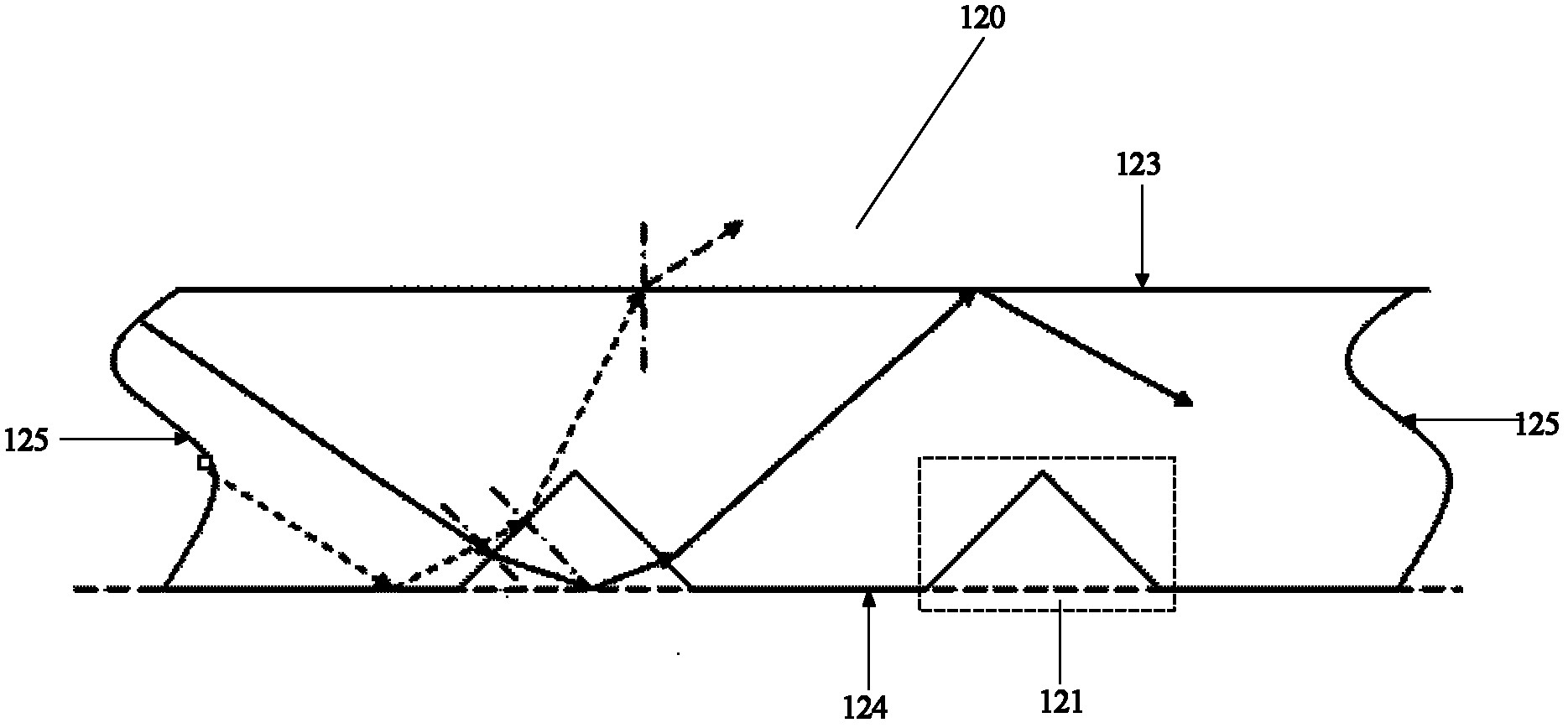
The invention provides a motor vehicle logo. The motor vehicle logo comprises a front shell, a light guide plate, a lining plate, a circuit board, and a back shell. The front shell is provided with a transparent region and a non-transparent region, wherein the transparent region is arranged to be of a predetermined logo shape. The light guide plate is arranged behind the front shell and provided with a plurality of microprism structures and one or a plurality of containing grooves, wherein the microprism structures are used for changing propagation direction of light inside the light guide plate so that the light can be emitted from a surface, opposite to the front shell, on the light guide plate. The lining plate is provided with one or a plurality of through holes, and one or a plurality of the through holes correspond to one or a plurality of the containing grooves. The circuit board is provided with one or a plurality of luminous bodies, wherein one or a plurality of the luminous bodies are embedded into one or a plurality of the containing grooves after penetrating through one or a plurality of the through holes. The back shell is connected with the front shell in a sealing mode, a containing space is formed by definition of the back shell and the front shell, and the containing space contains the light guide plate, the lining plate and the circuit board. The motor vehicle logo can emit light selectively, light-emitting effect is good, and the motor vehicle logo is attractive.

Description

technical field [0001] The invention relates to the field of automobiles, in particular to a motor vehicle logo. Background technique [0002] It is very difficult to realize the light emission of the existing car logo. It can only form a halo on the edge of the car logo pattern, but cannot reach the entire area of ​​the pattern. Therefore, although it has a certain decorative effect, due to the low brightness, especially in the light Inadequate or not easily recognized by other road users at night. [0003] Traditional car logos generally do not have a light-emitting function at night. When driving at night or when there is insufficient light, it is impossible to see the car logo clearly, let alone identify the brand of the motor vehicle. In the existing technology, such as application number 200920173796.5, the patent document entitled "Illuminated Automobile Logo and Its Light-emitting Components" introduces that a luminous component of the same shape is arranged on the ...

Claims


Application Information

Patent Timeline
IPC IPC(8): B60R13/00F21V13/02F21Y101/02F21Y115/10
Inventor 王金秋宋新新吴波宫清
Owner BYD CO LTD
Learn More