High-efficiency heat dissipating street lamp

A street lamp, high-efficiency technology, used in lighting and heating equipment, semiconductor devices for light-emitting elements, cooling/heating devices for lighting devices, etc. , Reasonable design effect

Inactive Publication Date: 2013-06-19
江苏尚恩光电科技有限公司
View PDF4 Cites 7 Cited by
  • Summary
  • Abstract
  • Description
  • Claims
  • Application Information

AI Technical Summary

Problems solved by technology

Because LED lamps cannot be made too large, with the demand for road lighting, the power of LED lamps is increasing, and the number of LED light sources per unit area installed on the cooling device is greatly limited

Method used


Image

  • High-efficiency heat dissipating street lamp
  • High-efficiency heat dissipating street lamp

Examples


Embodiment 1

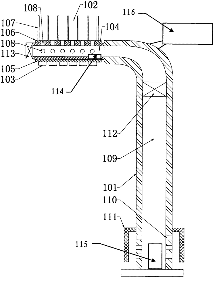
[0034] A high-efficiency heat dissipation street lamp, comprising a light pole 101, a heat dissipation device 102 directly or indirectly fixed on the light pole 101, and a plurality of LED light sources 103 fixed on the heat dissipation device 102; the heat dissipation device 102 includes a metal ventilation pipe 104, and the ventilation The tube 104 is flat and is a rectangular tube; the outer peripheral surface of the ventilation tube 104 is provided with an LED light source installation area 105 and a heat sink installation area 106; the heat sink installation area 106 is fixed with several heat sinks 107; the LED light source 103 installation area is located Bottom surface, and extend along the axial direction of ventilation pipe 104; There are 107 pieces; the light pole 101 is provided with an air-introduction channel 109, one end of the air-induction channel 109 is connected with one end of the ventilation pipe 104, and the air-induction channel 109 is provided with a num...

Embodiment 2

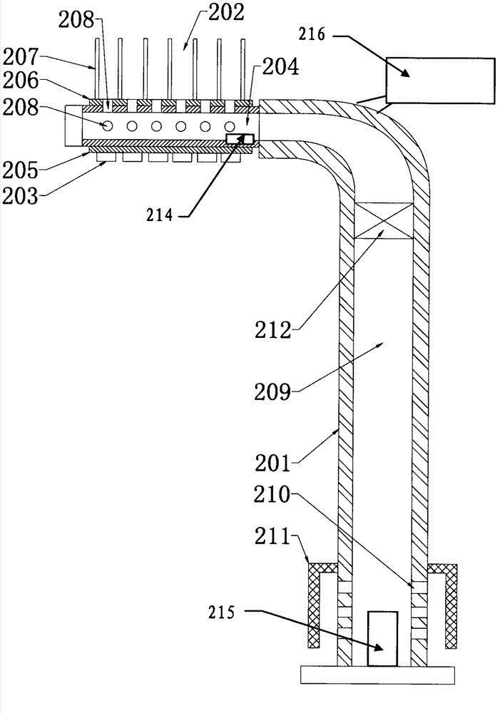
[0036] A high-efficiency heat dissipation street lamp, comprising a light pole 201, a heat dissipation device 202 directly or indirectly fixed on the light pole 201, and several LED light sources 203 fixed on the heat dissipation device 202; the heat dissipation device 202 includes a metal ventilation pipe 204, and the ventilation The tube 204 is flat and is a rectangular tube; the outer peripheral surface of the ventilation tube 204 is provided with an LED light source installation area 205 and a heat sink installation area 206; the heat sink installation area 206 is fixed with a number of heat sinks 207; Bottom surface, and extend along the axial direction of ventilation pipe 204; There are 207 pieces; the light pole 201 is provided with an air-introduction channel 209, one end of the air-induction channel 209 is connected with one end of the ventilation pipe 204, and the air-induction channel 209 is provided with a number of ventilation holes 210 that run through the light p...


PUM


Abstract

The invention discloses a high-efficiency heat dissipating street lamp. The high-efficiency heat dissipating street lamp comprises a lamp pole, a heat dissipating device which is directly or indirectly fixed on the lamp pole and a plurality of light-emitting diode (LED) light sources which are fixed on the heat dissipating device. The heat dissipating device comprises a metal vent pipe, and an LED light source installation area and a heat dissipating fin installation area are arranged on the peripheral surface of the vent pipe. A plurality of heat dissipating fins are fixed on the heat dissipating fin installation area, and a plurality of through holes which penetrate through the pipe wall of the vent pipe are arranged in the vent pipe. An induced air passage is arranged in the lamp pole, and one end of the induced air passage is communicated with one end of the vent pipe. A plurality of air holes which penetrate through the lamp pole are arranged in the induced air passage, and the air holes are arranged below the heat dissipating device. An induced draft fan is arranged in the induced air passage, and a temperature controlled switch which is used for controlling the induced draft fan is arranged in the heat dissipating device. According to the high-efficiency heat dissipating street lamp, the number of the installed LED light sources in a unit area on the heat dissipating device is increased under the condition that the size of the heat dissipating device is not enlarged. A cooling effect is improved along with the increase of quantity of heat produced by the LED light sources, and the high-efficiency heat dissipating street lamp is reasonable in design and low in cost, thereby being a better choice for energy conservation remolding of street lighting.

Description

technical field [0001] The invention relates to a street lamp, in particular to an efficient heat dissipation LED street lamp. Background technique [0002] In the field of street lamps, LED street lamps (Light Emitting Diodes, light-emitting diodes), that is, semiconductor lighting lamps, are high-efficiency solid-state light sources that can emit light with weak electric energy based on semiconductor PN junctions. And under the injection current, the holes injected into the P region and the electrons injected into the N region diffuse to the active region and emit photons through radiative recombination, which directly converts electrical energy into light energy. It is a solid-state cold light source, which has the characteristics of environmental protection, no pollution, low power consumption, high luminous efficiency, and long life. [0003] Following the proposal of "energy saving and emission reduction" and "low carbon", many domestic and foreign enterprises and res...

Claims


Application Information

Patent Timeline
Patent Type & Authority Applications(China)
IPC IPC(8): F21S8/08F21V29/02F21W131/103F21Y101/02F21V29/61F21V29/76F21Y103/10F21Y115/10
Inventor 叶剑锋叶萌竹
Owner 江苏尚恩光电科技有限公司
Why Eureka
Try Eureka