Eureka AIR delivers breakthrough ideas for toughest innovation challenges, trusted by R&D personnel around the world.

Parallel operation system of cooling towers with different areas

A technology of operation system and cooling tower, which is applied in the field of secondary circulation water supply system of power plants, can solve problems such as flow distribution, and achieve the effect of saving engineering investment

Inactive Publication Date: 2013-06-19
ANHUI ELECTRIC POWER DESIGN INST CEEC
View PDF5 Cites 2 Cited by
  • Summary
  • Abstract
  • Description
  • Claims
  • Application Information

AI Technical Summary

Problems solved by technology

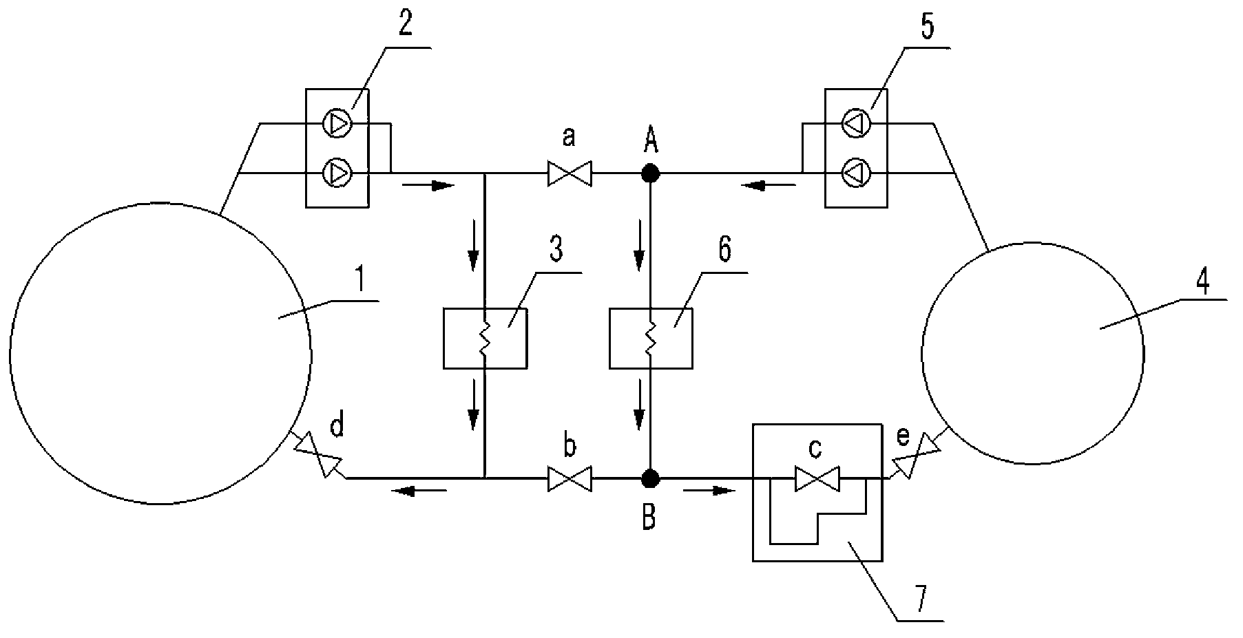
[0004] The present invention provides a parallel operation system of cooling towers with different areas and different water distribution heights in order to avoid the shortcomings of the above-mentioned prior art. By solving the problem of flow distribution of cooling towers with different areas in parallel operation, cooling The towers can be operated in parallel in the same system in order to effectively utilize the original cooling towers and save engineering investment

Method used


Image

  • Parallel operation system of cooling towers with different areas

Examples


Embodiment Construction

[0014] The parallel operation system of cooling towers with different areas in this embodiment is that the first cooling tower 4 and the second cooling tower 1 are jointly arranged in the system, and the cooling area C1 of the first cooling tower 4 is smaller than the cooling area C2 of the second cooling tower 1;

[0015] Such as figure 1 As shown, the specific settings of the system include:

[0016] In the water outlet circuit of the first cooling tower 4, according to the water flow direction, the first circulating water pump 5, the first cooler 6 and the resistance piece of the serpentine pipe are arranged in sequence, and the water outlet of the resistance piece of the serpentine pipe passes through the inlet valve of the first cooling tower e communicates with the water inlet of the first cooling tower 4; the serpentine pipe assembly is arranged in parallel with the serpentine pipe 7 and the serpentine bypass valve c;

[0017] In the water outlet circuit of the second ...


PUM


Abstract

The invention discloses a parallel operation system of cooling towers with different areas. The parallel operation system of the cooling towers with the different areas is characterized in that a first cooling tower and a second cooling tower are together arranged in the system, and the cooling area of the first cooling tower is less than the cooling area of the second cooling tower. According to the parallel operation system of the cooling towers with the different areas, a coil pipe resistance piece is arranged so that the cooling towers with the different areas are enabled to be put under an associated operating state, cooling capacity of the cooling towers which are originally needed to be wasted is fully used, and therefore construction investment of a newly-built power plant is saved.

Description

technical field [0001] The invention relates to a secondary circulation water supply system of a power plant. Background technique [0002] The design service life of power plants in my country is 20 years, while the service life of natural ventilation cooling towers is 30 years. With the continuous increase of energy conservation and emission reduction in my country, more and more small thermal power plants with a unit capacity of 125MW or less have been shut down to replace large thermal power units, and many of them have been put into operation for less than 10 years. For this type of power plant that is "upgrading the large and suppressing the small", the domestic practice is to dismantle all the small thermal power plants and rebuild a brand new power plant. Doing so would undoubtedly be wasteful, since there are many buildings or equipment that could be utilized. For example, a 125MW unit has a cooling tower area of ​​about 3500m 2 , the cost is about 20 million yua...

Claims


Application Information

Patent Timeline
Patent Type & Authority Applications(China)
IPC IPC(8): F28F27/02
Inventor 邬登林童林苏翔峰汪海郭解云陶应东王振海
Owner ANHUI ELECTRIC POWER DESIGN INST CEEC
Why Eureka
Eureka Blog
Learn More