
Method, device and system for obtaining vehicle three-dimensional outline

A three-dimensional profile and vehicle technology, applied in the field of measurement, can solve the problems of poor reliability, poor stability, small measurement range, etc., and achieve the effect of good stability, good reliability and simple algorithm

Active Publication Date: 2015-06-10
WUXI INSTITUTION OF INTERNET OF THINGS +1
View PDF4 Cites 0 Cited by
  • Summary
  • Abstract
  • Description
  • Claims
  • Application Information

AI Technical Summary

Problems solved by technology

[0005] In the process of implementing the present invention, the inventor found that this solution has at least the following disadvantages: the camera needs to take images in different orientations and then reconstruct a 3D object from the two captured 2D images, which requires harsh lighting conditions, low measurement accuracy, and reliable poor stability
[0007] In the process of implementing the present invention, the inventor found that although the solution solved the problems of harsh lighting conditions, low measurement accuracy, and poor reliability and stability, it had the advantages of non-contact, strong real-time performance, strong anti-interference ability, and high precision. But there are also the following disadvantages: all kinds of laser curtains used in this scheme are dedicated to measuring small-sized workpieces, and the measuring range is small. It is not suitable for larger objects such as vehicles, and the three-dimensional contour data of vehicles cannot be obtained.

Method used


Image

  • Method, device and system for obtaining vehicle three-dimensional outline
  • Method, device and system for obtaining vehicle three-dimensional outline
  • Method, device and system for obtaining vehicle three-dimensional outline

Examples


Embodiment 1

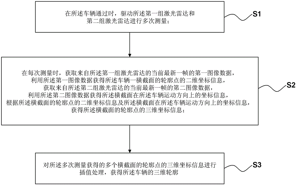
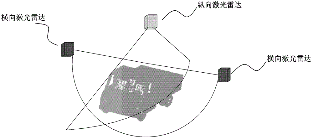
[0062] figure 1 It is a flow chart of the method in Embodiment 1 of the present invention, which is used in a system including a first group of laser radars and a second group of laser radars, wherein the first group of laser radars and the second group of laser radars are two-dimensional lasers The scanning surface of the first group of laser radars is perpendicular to the moving direction of the vehicle, and the scanning surface of the second group of laser radars is parallel to the moving direction of the vehicle.

[0063] The lidars in the first set of lidars may be referred to as lateral lidars, and the lidars in the second set of lidars may be referred to as longitudinal lidars. In this embodiment, both the horizontal laser radar and the vertical laser radar are two-dimensional laser radars. The two-dimensional laser radar emits a linear laser beam and uses high-frequency rotation to form a scanning surface. The reflection of the laser radar to obtain the position infor...

Embodiment 2

[0084] Figure 5 is a schematic diagram of the device in Embodiment 2, for a system including the first group of laser radars and the second group of laser radars, wherein

[0085] Both the first set of lidars and the second set of lidars are two-dimensional lidars, and

[0086] The scanning surface of the first group of laser radars is perpendicular to the moving direction of the vehicle, and the scanning surface of the second group of laser radars is parallel to the moving direction of the vehicle;

[0087] The devices include:

[0088] A control unit 501: used to drive the first group of laser radars and the second group of laser radars to perform multiple measurements when the vehicle passes by;

[0089] Lateral coordinate acquisition unit 502: used to drive the first group of laser radars to perform multiple measurements when the vehicle passes by, and acquire the first frame of the current latest frame from the first group of laser radars for each measurement. Image d...

Embodiment 3

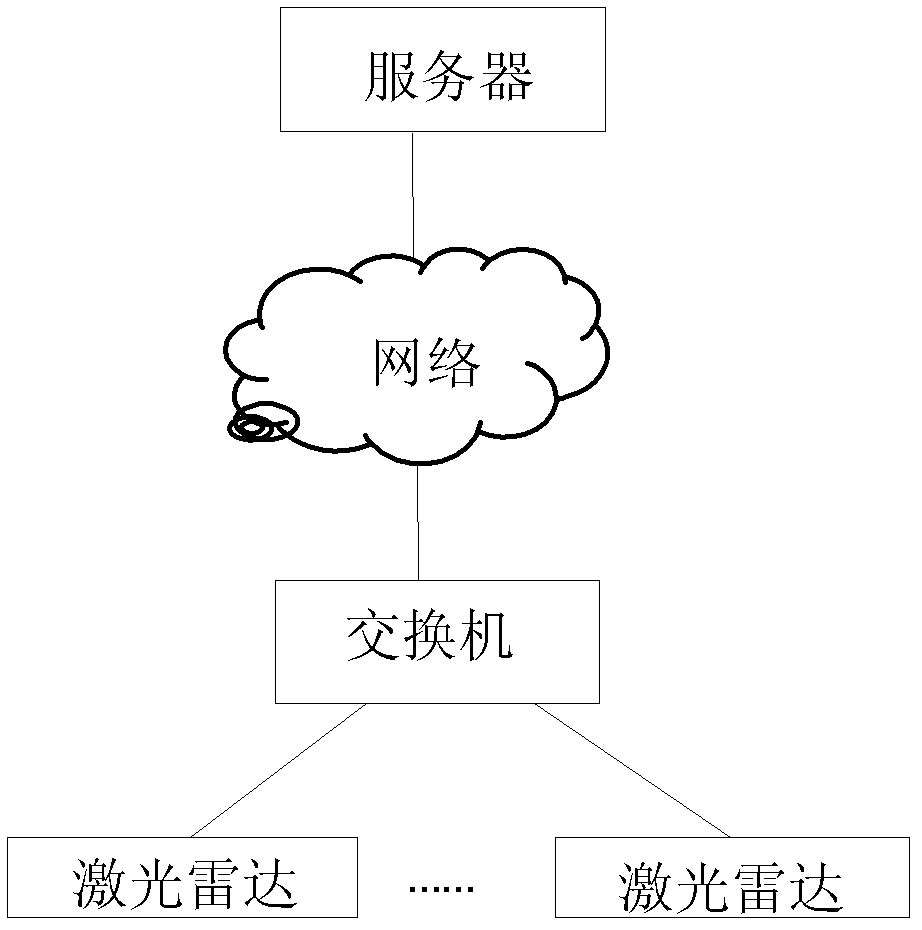
[0106] Figure 6 It is a schematic diagram of the system in Embodiment 3 of the present invention, including:

[0107] The first group of laser radar 601: it is a two-dimensional laser radar, and its scanning surface is perpendicular to the moving direction of the vehicle;

[0108] The second group of laser radar 602: it is a two-dimensional laser radar, and its scanning surface is parallel to the moving direction of the vehicle;

[0109] Processor 603: configured to drive the first group of laser radars and the second group of laser radars to perform multiple measurements when the vehicle passes by; drive the first group of laser radars to perform multiple measurements when the vehicle passes by, At each measurement, the first image data of the current latest frame from the first group of laser radars is obtained, and the two-dimensional coordinate information of the contour points of a cross section of the vehicle is obtained by using the first image data; When the vehicle...


PUM


Abstract

The invention discloses a method, a device and a system for obtaining a vehicle three-dimensional outline. In the method for obtaining the vehicle three-dimensional outline, scanning surfaces of first sets of laser radars are vertical to the moving direction of vehicles, and second sets of laser radars are parallel. The method for obtaining vehicle three-dimensional outline comprises the following steps: conducting multiple times measurement when vehicles pass; obtaining first image data of a current latest frame of the first set of laser radars in each measurement and obtaining two-dimensional coordinate information of outline points of cross sections of the vehicles; obtaining second image data of a current latest frame of the second set of laser radars and obtaining coordinate information of the outline points in the moving direction of the vehicles; then obtaining three-dimensional coordinate information of the outline points of the cross sections according to the two-dimensional coordinate information and the coordinate information of the outline points in the moving direction of the vehicles; lastly conducting interpolation treatment on the three-dimensional information of the outline points of a plurality of cross sections of multiple times measurement and conducting three-dimensional outlines of the vehicles. According to the method for obtaining the vehicle three-dimensional outline, accurate three-dimensional outline data of the vehicles can be obtained.

Description

technical field [0001] The invention relates to the field of measurement, in particular to a method, device and system for acquiring a three-dimensional profile of a vehicle. Background technique [0002] In the road transportation industry, illegal modification of vehicles such as over-length, over-width, and over-height often occurs. Such over-limit transportation of vehicles often directly leads to overloading, which easily leads to problems such as road traffic accidents and early damage to road facilities. At present, the country also has corresponding laws and regulations that clearly stipulate that the structure of the vehicle must not be arbitrarily modified, and it is strictly forbidden to exceed the limit. The length, width, and height of the load must not violate the loading requirements. Important content of parameters and operation safety inspection. [0003] At present, the measuring instruments commonly used by my country's automobile inspection institutions ...

Claims


Application Information

Patent Timeline
Patent Type & Authority Patents(China)
IPC IPC(8): G01B11/24G01S17/89
Inventor 邵长东余志军何风行吕政马润泽高彦潘强沈杰刘海涛
Owner WUXI INSTITUTION OF INTERNET OF THINGS
Learn More