Method for controlling automatic detection of leakage rate of vacuum chamber

A vacuum chamber, automatic detection technology, applied in the direction of detecting the occurrence of fluid at the leak point, using liquid/vacuum for liquid tightness measurement, semiconductor/solid device manufacturing, etc., can solve pollution, production capacity and yield decline, Issues such as technical solutions for leak detection are not mentioned to achieve the effect of simplifying the subsequent process and making up for the waste of gas

Inactive Publication Date: 2013-06-19
EVERDISPLAY OPTRONICS (SHANGHAI) CO LTD
View PDF8 Cites 0 Cited by
  • Summary
  • Abstract
  • Description
  • Claims
  • Application Information

AI Technical Summary

Problems solved by technology

[0002] The method of automatic detection of leak rate in existing vacuum cavity is as follows: figure 1 As shown, the steps of leak rate detection and self-cleaning are separated, as in figure 2 In the traditional vacuum chamber automatic leak rate detection equipment shown, the cleaning detection part and the leak rate detection part are not connected together, which directly causes gas waste, production and yield reduction, and pollution in subsequent processes.
[0003] Chinese patent (CN101839794A) discloses a method and system for batch vacuum leak detection of large vacuum chambers, in which it is mentioned that when performing leak detection on large vacuum chambers, first rough vacuuming and then use a high-precision leak detector to detect leaks method, but did not mention the technical solution for leak detection, nor did it mention the technical solution for self-cleaning after shutdown
However, the method of detecting the leak rate used in the patent does not mention the process of self-cleaning

Method used


Image

  • Method for controlling automatic detection of leakage rate of vacuum chamber
  • Method for controlling automatic detection of leakage rate of vacuum chamber
  • Method for controlling automatic detection of leakage rate of vacuum chamber

Examples


Embodiment Construction

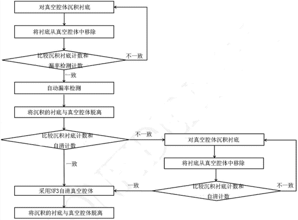
[0028] The present invention will be further described below with reference to the drawings and specific embodiments, but it is not a limitation of the present invention.

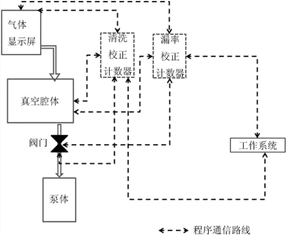
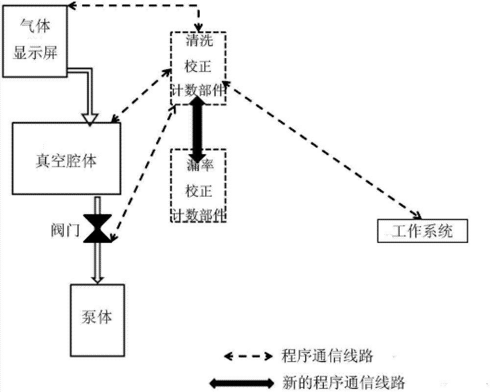
[0029] Such as image 3 As shown, in the embodiment of the present invention, the new type of basic equipment for automatically detecting leak rate (ie, the vacuum chamber detection system) includes a vacuum chamber and a counter for detecting the leak rate. The vacuum chamber is connected to a gas display screen and passes A valve is connected to a pump body; the counter includes two interconnected parts: a cleaning calibration counting component and a leak rate calibration counting component. The cleaning calibration counting component is respectively connected to the vacuum chamber, the gas display screen and the external working system, and passes through the valve Connect the pump body.

[0030] The cleaning correction counting component is used to calculate the self-cleaning count; the leak rate correction...


PUM


Abstract

The invention discloses a method for controlling automatic detection of the leakage rate of a vacuum chamber, belongs to the technical field of vacuum chambers, and is applied to a vacuum chamber detecting system. The vacuum chamber detecting system comprises the vacuum chamber, a pump and a counter, the vacuum chamber is connected with the counter, the counter is connected with an external operating system, the vacuum chamber is further connected with the pump through a valve, and the pump is connected with the counter through a valve. The method includes the steps: depositing substrates on the vacuum chamber; removing the substrates; comparing a deposited substrate count with a self-cleaning count; continuing to compare the deposited substrate count with a leakage rate detecting count if the deposited substrate count is consistent with the self-cleaning count; detecting the leakage rate of the vacuum chamber if the deposited substrate count is consistent with the leakage rate detecting count; self-cleaning the vacuum chamber; and detaching the deposited substrates from the vacuum chamber. By the aid of the technical scheme, the method has the advantages that the follow-up manufacture procedure of detecting the leakage rate of the vacuum chamber is simplified, and the shortcomings of gas waste and productivity and yield reduction of the follow-up manufacture procedure in the prior art are overcome.

Description

Technical field [0001] The invention relates to the technical field of vacuum chambers, and in particular to a method for controlling and automatically detecting leakage rates of a vacuum chamber. Background technique [0002] The existing methods for automatically detecting the leak rate of the vacuum chamber are as follows: figure 1 As shown, the steps of leak rate detection and self-cleaning are separated. figure 2 In the shown conventional vacuum chamber automatic leak rate detection equipment, the cleaning detection component and the leak rate detection component are not connected together, which directly causes gas waste, productivity and yield reduction in subsequent processes, and pollution. [0003] The Chinese patent (CN101839794A) discloses a method and system for batch vacuum leak detection of large vacuum chambers, which mentions the method of first vacuuming the large vacuum chamber for leak detection and then using a high-precision leak detector to detect leaks. Met...

Claims


Application Information

Patent Timeline
IPC IPC(8): G01M3/02G01M3/20H01L21/67
Inventor 黄德伦
Owner EVERDISPLAY OPTRONICS (SHANGHAI) CO LTD
Why Eureka
Try Eureka