Discharge ionization current detector

A current detector and discharge ionization technology, applied in the field of discharge ionization current detectors, can solve the problems of wide dynamic range, low dynamic range, and insufficient FID detectable amount.

Active Publication Date: 2013-06-19
SHIMADZU SEISAKUSHO CO LTD
View PDF11 Cites 11 Cited by
  • Summary
  • Abstract
  • Description
  • Claims
  • Application Information

AI Technical Summary

Problems solved by technology

However, FID has the following defects: (1) the ionization efficiency of FID is low, which makes the minimum detectable amount of FID not low enough; (2) the ionization efficiency of FID for alcohols, aromatic substances and chlorine-containing substances is low; ( 3) FID requires hydrogen as a highly dangerous substance, so it is necessary to set up explosion-proof equipment or similar kind of special equipment, which makes the whole system more difficult to operate
However, the dynamic range of the PDD is not as wide as that of the FID; in fact, the dynamic range of the PDD is one or more orders of magnitude lower than that of the FID

Method used


Image

  • Discharge ionization current detector
  • Discharge ionization current detector
  • Discharge ionization current detector

Examples


no. 1 example

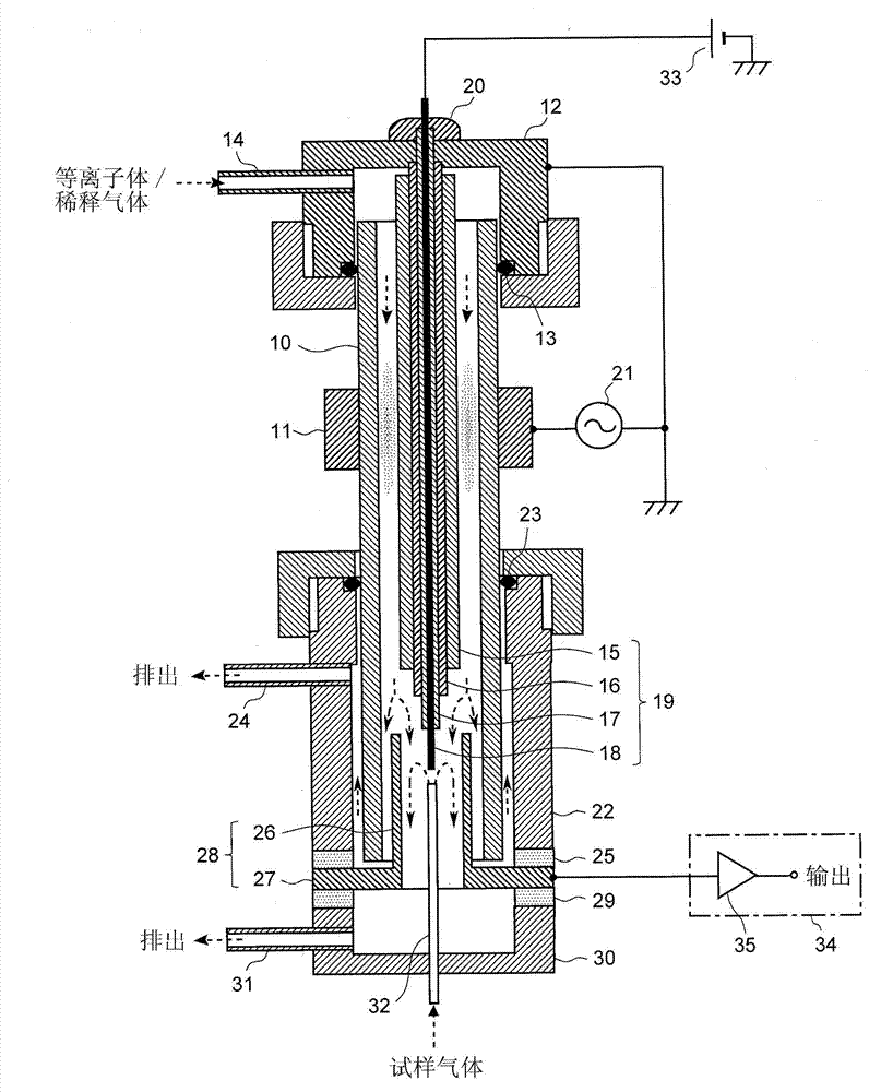
[0096] The following reference figure 1 A discharge ionization current detector according to an embodiment (first embodiment) of the present invention will be described. figure 1 is a schematic configuration diagram of the discharge ionization current detector according to the first embodiment.

[0097]The discharge ionization current detector of this embodiment has an outer dielectric tube 10 ("dielectric tube" in this embodiment) made of a dielectric material such as quartz. For example, as the outer dielectric tube 10, a quartz tube having an outer diameter of 7 mm and an inner diameter of 5 mm can be used. On the outer surface of the outer dielectric tube 10, a ring-shaped electrode 11 ("plasma generation excitation electrode" in this embodiment) made of metal (for example, stainless steel or copper) is provided circumferentially.

[0098] An upper side adapter 12 in the form of a cylinder whose upper side is closed and whose lower side is open is attached to the upper...

no. 2 example

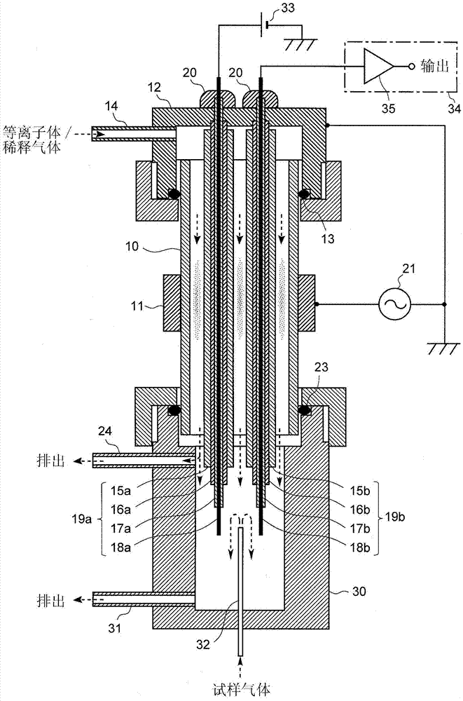
[0119] The following reference figure 2 A discharge ionization current detector according to another embodiment (second embodiment) of the present invention will be described. figure 2 is a schematic configuration diagram of a discharge ionization current detector according to the second embodiment. In this figure, the same components as those used in the first embodiment are denoted by the same reference numerals, and explanations for these components will be appropriately omitted.

[0120] The discharge ionization current detector according to this embodiment is different from the first embodiment in that the detector has two electrode structures in which no flanged metal tube is used and the An integral assembly (hereinafter referred to as "lower adapter 30") replaces the intermediate adapter and the lower adapter.

[0121] The two electrode structures in this embodiment (hereinafter referred to as "first electrode structure 19a" and "second electrode structure 19b") ea...


PUM


Abstract

A discharge ionization current detector that is durable and produced at a low cost is provided. An electrode structure of a dielectric-coated metal tube, with an insulator-coated metal wire included therein, is inserted from above into a first gas passage including a dielectric tube. The metal tube is connected to the ground on the upstream side of the first gas passage. One end of the metal wire is extracted from the upstream side of the first gas passage to the outside and connected to a bias power source. An area is not covered with the insulator is provided at the other end of the wire. This area is arranged in a second gas passage, which extends from the downstream end of the first gas passage. A metal electrode consisting of a flanged metal tube is placed in the second gas passage and connected to an ionization current detecting circuit 34.

Description

technical field [0001] The present invention relates to a discharge ionization current detector suitable primarily as a gas chromatography (GC) detector, and more particularly to a discharge ionization current detector using a low frequency barrier discharge. Background technique [0002] As gas chromatography detectors, such as thermal conductivity cell detector (TCD), electron capture detector (ECD), flame ionization detector (FID), flame photometric detector (FPD) and flame thermionic detector have been practically used (FTD), etc. of various types of detectors. Among these detectors, FIDs are most widely used, especially for the purpose of detecting organic substances. The FID is a device that uses a hydrogen flame to ionize the sample components in the sample gas and detects the resulting ionization current. The FID can achieve a wide dynamic range of about 6 orders of magnitude. However, FID has the following defects: (1) the ionization efficiency of FID is low, whi...

Claims


Application Information

Patent Timeline
Patent Type & Authority Applications(China)
IPC IPC(8): G01N30/68
CPCG01N27/70G01N27/60G01N27/66G01N30/64
Inventor 品田惠堀池重吉
Owner SHIMADZU SEISAKUSHO CO LTD
Why Eureka
Try Eureka