Speech enhancement method of microphone array under non-stationary noise environment

A microphone array, non-stationary noise technology, applied in speech analysis, instruments, etc., can solve the problems of limited performance, inferior performance and limited suppression effect of speech enhancement technology

Active Publication Date: 2013-06-19
IOASONIC SU ZHOU TECH CO LTD
View PDF5 Cites 20 Cited by
  • Summary
  • Abstract
  • Description
  • Claims
  • Application Information

AI Technical Summary

Problems solved by technology

However, due to the existence of background noise, interference noise and echo, the signal-to-noise ratio of the picked-up speech is usually low, and the speech enhancement technology based on the microphone array is one of the common means to improve the signal-to-noise ratio of the received speech
[0003] At present, there are two main types of microphone array speech enhancement technologies. One is based on conventional beamforming. The beam shape of this method is fixed and will not change with the change of the interfering sound signal. For example, the reverberation sound has a better suppression effect, and the speech enhancement performance improves with the increase of the number of microphones, but the suppression effect on directional interference noise is limited; the other type is based on an adaptive beamforming algorithm, and its beam shape will vary with The adaptive beamforming algorithm can effectively suppress the directional interference noise, but in the weakly correlated noise field or in the scattered noise field, the performance is not as good as the traditional beamforming algorithm.
The above two algorithms usually require the interference noise to be a stationary process. However, in the actual use environment, the interference noise is usually sudden and non-stationary, such as speech interference. In this case, most of the current speech enhancement technologies have limited performance.

Method used


Image

  • Speech enhancement method of microphone array under non-stationary noise environment
  • Speech enhancement method of microphone array under non-stationary noise environment
  • Speech enhancement method of microphone array under non-stationary noise environment

Examples


Embodiment Construction

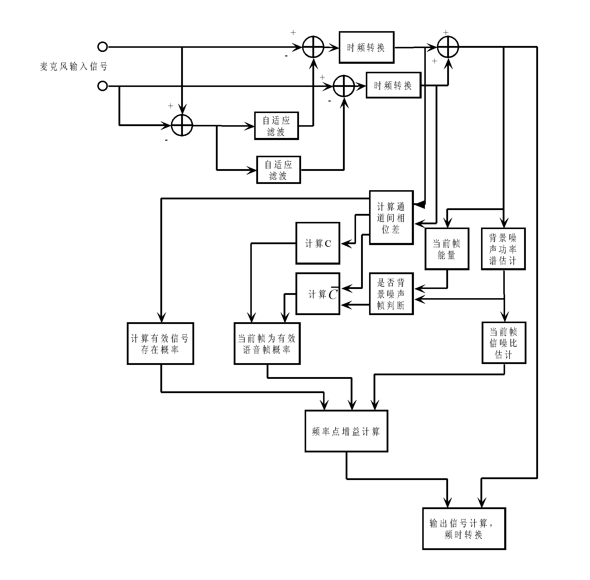
[0056] The microphone array speech enhancement method of the present invention is described with a specific embodiment. In the embodiment, the number of microphone array units is 2, the spacing is 8 cm, the beam width is 10 degrees, and the sampling frequency is 16000 Hz.

[0057] Such as figure 1 As shown, first, the reference background noise signal is calculated from the two microphone input signals:

[0058] r(n)=x 1 (n)-x 2 (n);

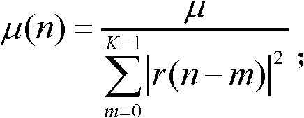
[0059] where x i (n) represents the input signal of the i-th microphone at time n. The background noise signal is used as a reference signal to perform adaptive filtering on the microphone signal to initially remove the noise in the microphone input signal. The adaptive filtering algorithm can use the commonly used NLMS algorithm, and the specific description is as follows:

[0060] w i (k,n)=w i (k,n-1)-μ(n)e i (n)n(n) k=0...K-1

[0061] μ ( n ) = μ...


PUM


Abstract

The invention relates to a speech enhancement method of a microphone array under a non-stationary noise environment. The probability of an effective signal is accurately judged by means of phase information between passageways in order to improve non-stationary noise environment interference resistant performance. The method which estimates the probability of the effective signal specifically comprises the following steps: (51) according to a required beam width, calculating a threshold T1=NL sin (theta)/Fs, wherein N represents frame length, L represents microphone unit distance, theta represents beam width, and Fs represents sample frequency, (52) calculating the valve of the sum of phase differences omega of input signals of all passageways on all frequency points pd (n, omega); and (53) when the pd (n, omega)>omega (M-1) T1, the effective signal probability exists on the frequency point p1 (n, omega)=1, otherwise, p1 (n, omega)=0, wherein M represents the number of microphones. Due to the fact that the phase information between the passageways is used, judgment to the probability of the effective signal is enabled to be more accurate, the signal to noise ratio of picked up voice is improved, whole performance is improved, and particularly non-stationary noise environment interference resistant performance is improved.

Description

technical field [0001] The invention relates to the field of microphone array voice enhancement, in particular to a microphone array voice enhancement method in a non-stationary noise environment. Background technique [0002] In applications such as video conferencing systems, vehicle hands-free systems, and speech recognition systems, it is usually necessary to pick up the target voice at a relatively long distance. However, due to the existence of background noise, interference noise and echo, the signal-to-noise ratio of the picked-up speech is usually low, and the speech enhancement technology based on the microphone array is one of the common means to improve the signal-to-noise ratio of the received speech. [0003] At present, there are two main types of microphone array speech enhancement technologies. One is based on conventional beamforming. The beam shape of this method is fixed and will not change with the change of the interfering sound signal. For example, th...

Claims


Application Information

Patent Timeline
Patent Type & Authority Applications(China)
IPC IPC(8): G10L21/0208
Inventor 吴鸣杨飞然杨军
Owner IOASONIC SU ZHOU TECH CO LTD
Why Eureka
Try Eureka