Automatic braking device of gardening tool

A technology for automatic braking and garden tools, applied in agricultural machinery and implements, applications, harvesters, etc., can solve problems such as failure to meet safety requirements, failure to stop rotation, and poor braking effect, and achieve good braking effect. Stable and reliable work, simple structure

Active Publication Date: 2013-06-26
ZHEJIANG SAFUN IND
View PDF9 Cites 5 Cited by
  • Summary
  • Abstract
  • Description
  • Claims
  • Application Information

AI Technical Summary

Problems solved by technology

The disadvantage of this structure is: when braking, the centrifugal force of the brake pads is less than the pressure of the spring, and the brake pads are brought into contact with the friction ring only by the restoring force of the spring to achieve braking.
Although braking can

Method used


Image

  • Automatic braking device of gardening tool
  • Automatic braking device of gardening tool
  • Automatic braking device of gardening tool

Examples


Embodiment Construction

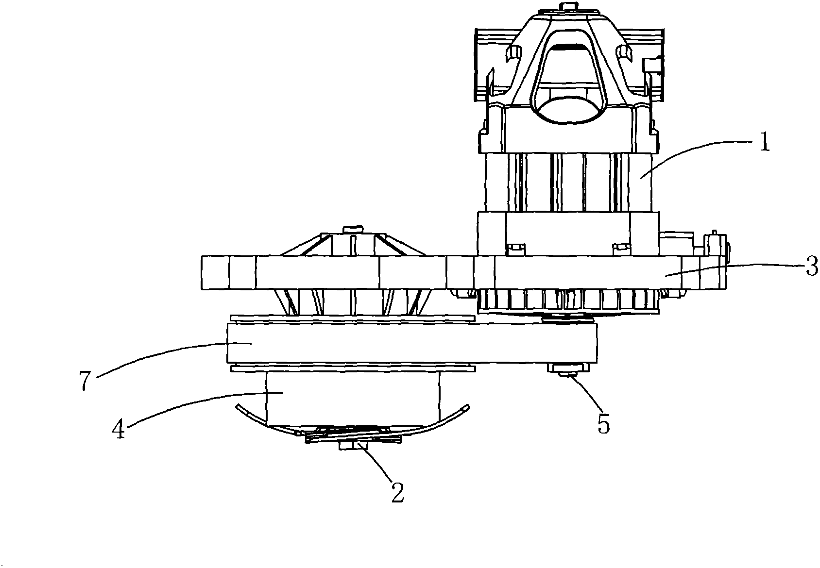
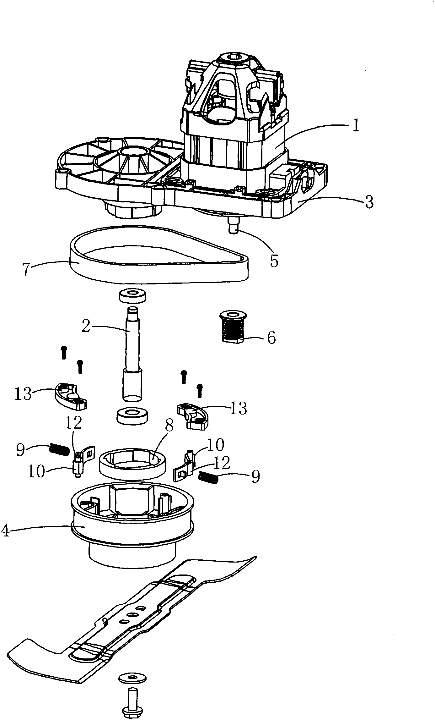
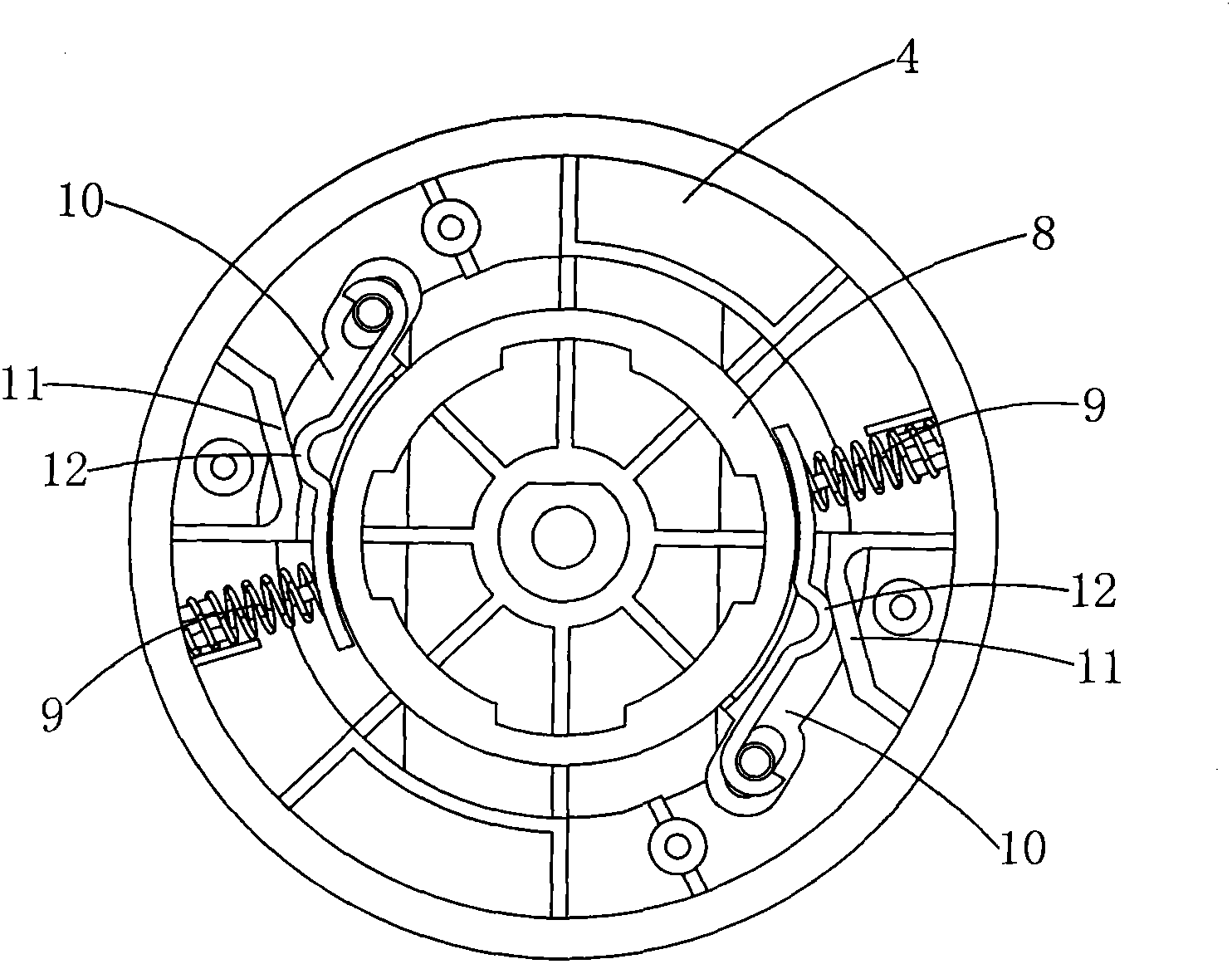
[0017] see Figure 1 to Figure 3 According to the automatic braking device of the garden tool provided by the present invention, it includes a fixed plate 3 with a motor 1 and an output shaft 2, a large pulley 4 is fixed on the output shaft 2, and the lower end of the motor shaft 5 protrudes from the fixed plate 3 and is fixed. There is a small pulley 6, a large pulley 4 and a small pulley 6 are connected through a transmission belt 7, and the fixed plate 3 is fixed with a friction ring 8 that is sleeved on the output shaft 2 and extends into the large pulley 4, and the large pulley 4 The inner cavity of the inner cavity is provided with a spring 9 and a brake pad 10, one end of the brake pad 10 is movably connected with the large pulley 4, and the other end is matched with the spring 9, the inner cavity of the large pulley 4 is also provided with a stop slope 11, the brake pad 10 is provided with a protrusion 12, and the protrusion 12 can slide on the stop slope 11. When work...


PUM


Abstract

An automatic braking device of a gardening tool comprises a fixing plate, wherein a motor and an output shaft are arranged on the fixing plate. A big belt wheel is fixed on the output shaft. The lower end of a shaft of the motor stretches out of the fixing plate and a small belt wheel is fixed on the lower end of the shaft of the motor. The big belt wheel is connected with the small belt wheel in a transmission mode through a transmission belt. A friction ring sleeved on the output shaft and stretching into the big belt wheel is fixed on the fixing plate. A spring and a braking block are arranged in an inner cavity of the big belt wheel. One end of the braking block is movably connected with the big belt wheel. The other end of the braking block is matched with the spring in an abutting mode. A check slope is further arranged in the inner cavity of the big belt wheel. A protrusion is arranged on the braking block and is capable of sliding on the check slope. The automatic braking device of the gardening tool has the advantages of being simple in structure, high in safety, good in braking effect, low in production cost, long in service life, stable and reliable in working, and the like.

Description

Technical field: [0001] The invention relates to an automatic braking device for a garden tool, in particular to an automatic braking device for a lawnmower. Background technique: [0002] The lawnmower is a commonly used garden power tool, and the motor is used as the driving device to drive the output shaft that the blade is installed by a belt or a gear transmission to perform operations. If it is necessary to stop during the operation, the operator must first cut off the power. After the power is cut off, due to the inertia, the output shaft and the blade will still run at high speed for a period of time, so it cannot meet the safety requirements, and even cause personal injury in severe cases. . In the design index, it is required that the blade can stop rotating within 3-5 seconds after the power is cut off, so manufacturers have brake devices installed on the lawn mower. Currently on the market, the brake device of the lawn mower is equipped with a radially movable ...

Claims


Application Information

Patent Timeline
IPC IPC(8): A01D69/10
Inventor 孙亮亮
Owner ZHEJIANG SAFUN IND
Why Eureka
Try Eureka