Common wall structure of reactor and flue gas inlet pipe in flue gas denitrification system

A reactor and denitrification technology, applied in chemical instruments and methods, exhaust gas devices, lighting and heating equipment, etc., can solve the problems of increasing equipment cost and maintenance cost, increasing the amount of supporting steel, high cost and heat preservation cost, and reducing equipment Quantity and corresponding maintenance costs, reducing space requirements, and ensuring the effect of structural safety

Active Publication Date: 2015-11-04
WUHAN LONGKING ENVIRONMENTAL PROTECTION CO LTD
View PDF2 Cites 0 Cited by
  • Summary
  • Abstract
  • Description
  • Claims
  • Application Information

AI Technical Summary

Problems solved by technology

This type of structure has the following disadvantages: the expansion joint at the connection between the reactor 1 and the smoke inlet pipe 2 increases the equipment cost and the corresponding maintenance cost of the equipment; it is necessary to add support brackets 10 to support the smoke inlet pipe 2, which will correspondingly Increase the amount of supporting steel; In order to form a closed structure and withstand the corresponding flue gas pressure, the reactor 1 and the smoke inlet pipe 2 need to be equipped with independent flue wall plates and corresponding stiffeners Ribs, this structure will lead to a large amount of steel, and correspondingly, the cost and heat preservation cost of the outer guard plate arranged on the reactor 1 and the smoke inlet pipe 2 are relatively high; There are requirements for support structure and thermal insulation construction, etc. Usually, it is required to leave a space of 1.2m-1.5m between the two flue wall panels. m space influenced the implementation of the retrofit

Method used


Image

  • Common wall structure of reactor and flue gas inlet pipe in flue gas denitrification system
  • Common wall structure of reactor and flue gas inlet pipe in flue gas denitrification system
  • Common wall structure of reactor and flue gas inlet pipe in flue gas denitrification system

Examples


Embodiment Construction

[0020] The implementation of the present invention will be described in detail below in conjunction with the accompanying drawings, but they do not constitute a limitation to the present invention, and are only examples. At the same time, the advantages of the present invention will become clearer and easier to understand through the description.

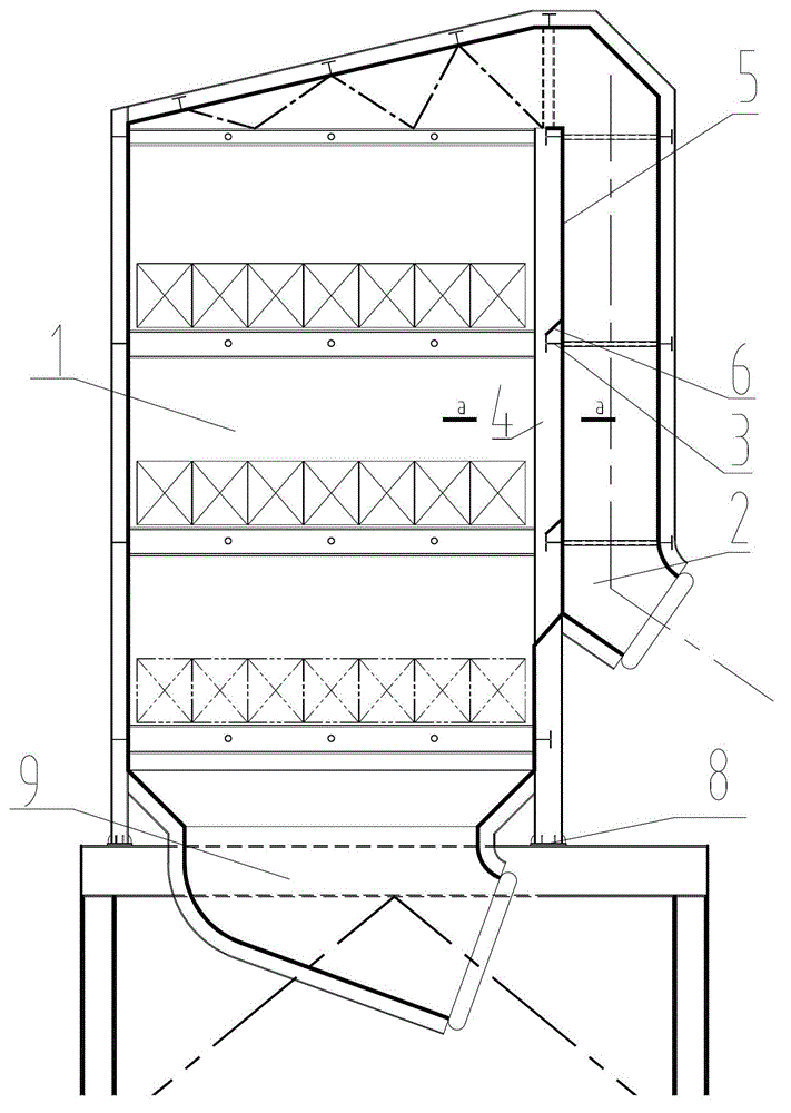
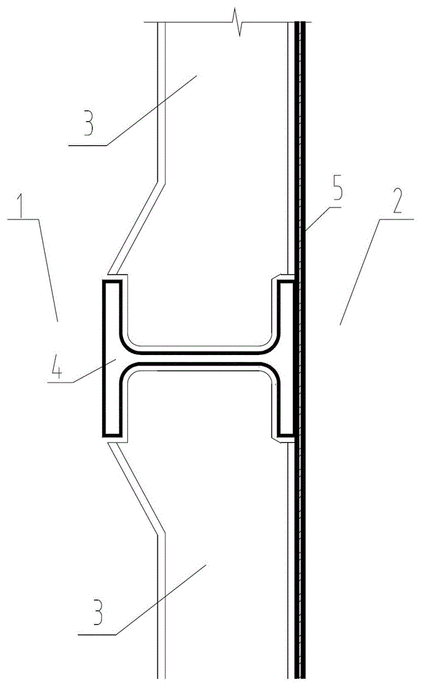
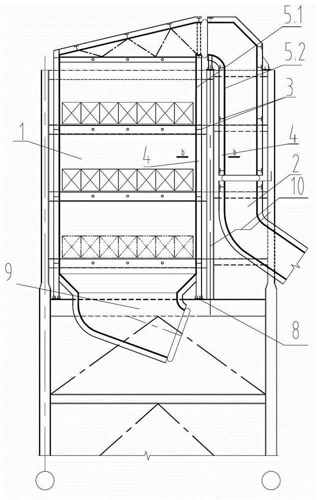
[0021] Referring to the accompanying drawings, it can be seen that the common wall structure of the reactor and the flue gas inlet pipe in the flue gas denitrification system includes the reactor 1 and the flue gas inlet pipe 2, and the lower end of the reactor 1 is correspondingly extended by its vertical stiffener 4 as the reactor support. Seat 8, the lower end of the reactor support 8 is provided with a reactor support layer girder 9, the reactor 1 is provided with a flue wall plate 5, the vertical stiffener 3 connected with the flue wall plate 5, and the vertical stiffener The horizontal stiffening ribs 4 connected with the ribs...


PUM


Abstract

The invention discloses a shared-wall structure of a reactor and a smoke inlet pipeline in a smoke denitration system. The shared-wall structure comprises the reactor (1) and the smoke inlet pipeline (2) and is characterized in that a flue wall plate (5), vertical reinforcement ribs (3) connected with the flue wall plate (5) and horizontal reinforcement ribs (4) connected with the vertical reinforcement ribs (3) are arranged on the reactor (1); and the smoke inlet pipeline (2) is connected with the flue wall plate (5) of the reactor (1). By the shared-wall structure of the reactor and the smoke inlet pipeline in the smoke denitration system, the number of equipment and the corresponding maintenance cost are effectively reduced, and the using amounts of steel materials, heat preservation materials and outer protection plate materials are reduced; the requirement on a space during denitration modification is reduced; the structural safety is guaranteed; and the corresponding engineering construction, running and maintenance cost is reduced.

Description

technical field [0001] The invention relates to selective catalytic reduction (SCR) denitrification technology, in particular to a common-wall structure of a reactor and a smoke inlet pipe in a flue gas denitrification system. Background technique [0002] Most of our electricity comes from burning fossil fuels. The source of fossil fuels is unstable, and the quality is also unstable. For every ton of coal burned, about 5-30kg of nitrogen oxides are produced. Power plant boilers have become one of the main fixed sources of air pollution. [0003] In order to improve the quality of the atmospheric environment, the state and some local governments have formulated increasingly stringent nitrogen oxide emission standards for the thermal power industry, requiring measures to be taken for pollution control. "Emission Standards of Air Pollutants for Thermal Power Plants" (GB13223-2011) requires that the NOx emission concentration of units put into operation before 2013 should not ...

Claims


Application Information

Patent Timeline
Patent Type & Authority Patents(China)
IPC IPC(8): B01D53/90B01D53/56F23J11/00
Inventor 索生雄吴雪萍霍德武廖本森
Owner WUHAN LONGKING ENVIRONMENTAL PROTECTION CO LTD
Why Eureka
Try Eureka